


Introduction
Precision and reliability are not just the desirable qualities in the world of manufacturing, but they are the necessities. The toggle clamp is a deceptively simple, but very important tool at the core of many fabrication, assembly, and testing processes. It is a simple tool, whose purpose is to hold a workpiece in place. But it is anything but trivial to know what force it actually produces, the clamping force. The wrong estimation of this force may result in disastrous failures, low quality of products or, at least, inefficient operations.
This paper explores the mechanics, mathematics, and manufacturing reality of the force of a toggle clamp. We shall cut up the theoretical maximums, face the unavoidable loss of efficiency, and give a clear methodology of determining the actual required clamping force. It is our hope that by filling the gap between textbook basic formula and actual performance we will enable the engineers, machinists and procurement specialists to have the knowledge they need to choose and use these invaluable tools with complete confidence for their specific application.We will begin with the principles of leverage and then proceed to the stringent testing procedures that are used by the market leaders such as Kunlong to guarantee reliability that can withstand the demands of the high-stakes industrial settings.
What is Toggle Clamp Force
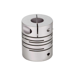
Toggle clamp force is the pressure or securing force that is directly applied to the workpiece by the spindle or pad of the clamp mechanism when the clamp mechanism is fully engaged and locked over-center. This is also commonly referred to as the clamp load.
The principle of the toggle action, a particular form of four-bar linkage mechanism, is used to create this force. The condition in which the two central links of the mechanism are aligned to create a straight line (the over-center position) is called a toggle. This is essential since, as the links approach the line, a small input amount of force exerted by the operator (or actuator) is multiplied by a very large number of times at the spindle, due to the near-infinite mechanical advantage of the geometry just prior to locking. This trait is commonly compared to a minor change that opens a dam of gaining power, which offers a firm grip with little effort. The design of the clamp is such that when the mechanism has over-centered, the force is held constant and safe and cannot be dislodged until the clamp is unlocked intentionally.
.webp)
Toggle Clamp Holding Capacity What is Toggle Clamp Holding Capacity
Although the terms are used interchangeably in everyday language, there is an important distinction that needs to be made between Toggle Clamp Force and Toggle Clamp Holding Capacity.
- Holding Capacity (or Nominal Capacity): This is the maximum holding capacity or the maximum clamp force that the structure of the clamp can sustain before it undergoes permanent deformation of the clamp components or mechanical damage. It is a value that is usually given by the manufacturer and is mainly used as a structural limit or a safety rating. This figure is usually determined by the application of a constant load until the clamp arm or base becomes permanently deformed or fractured.
- Clamping Force (or Working Force): This is the resulting clamping force that is actually used by the clamp on the workpiece, which can also be described as the effective amount of force delivered. It is the force that can be used in the practical work of holding. Importantly, the effective clamping force is nearly always much less than the quoted holding capacity because of the losses of mechanical efficiency (friction, material flex, etc.) in the linkage system.
Simply put, the holding capacity informs you of what the clamp can take before failure and the clamping force informs you of what the clamp provides to the part. Never use the nominal holding capacity to design your application but use the calculated clamping force. Misidentifying the two is an engineering error that is similar to the one of confusing the maximum speed that a tire can theoretically sustain with the real speed limit on the road.
The Significance of Clamping Force Calculation
Proper determination of clamping force is of utmost importance due to a number of operational reasons:
- Workpiece Security: The main aim is to ensure that the workpiece does not move, vibrate, or lift during the process such as machining, welding, or assembly. Lack of clamping force causes chatter, dimensional errors or even the disastrous ejection of the part.
- Tool and Equipment Protection: The workpiece may move, resulting in the premature breakage of tools (e.g. cutting inserts), which damages costly equipment and causes a lot of downtime.
- Consistency and Quality Control: Processes must be repeatable. When the clamping force is not constant, the quality of the part will not be the same. Calculation gives a measurable, reproducible measure of setup.
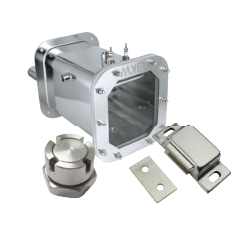
- Avoiding Part Deformation: Overloading may cause crushing, denting, or deformation of delicate or thin-walled workpieces. For example, in plastic molding, excessive clamping might affect the final part’s wall thickness or cause flash, though the necessary cavity pressure must be resisted. Proper calculation will make the force used adequate to hold and at the same time gentle enough to maintain the integrity of the part- a delicate balance between grip and grace.
.webp)
Calculation of Clamping Force
The theoretical maximum clamping force is calculated based on the basic physics of lever and the concept of mechanical advantage. A toggle clamp is a compound lever system. The product of the mechanical advantages of the lever systems which make it up, leading to the critical toggle action, is the overall force multiplication. This principle is also foundational to the mechanics of a bolted joint where an axial force is created by applying an amount of torque to a threaded fastener.
The theoretical maximum clamping force is a simple, but idealized basic formula based on the principle of Nominal Force Multiplication. This is a geometric ratio of the force multiplication based on the lengths of the handle (input) and the linkage (output) when operating perfectly and without friction.
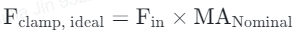
Where:
- F clamp, ideal is Theoretical Clamping Force.
- F in is the Input Force (The force exerted by the operator or actuator).
- MA Nominal is the Nominal Mechanical Advantage or Force Multiplication Factor, which is usually provided in the specification sheets of the manufacturer, based on the geometry of the links as the mechanism approaches the over-center lock.
The maximum mechanical advantage occurs when the two central links are in line ( a→0). This is where the huge leverage comes in. In the case of a typical manual clamp, the input force (F in ) is the force applied by the hand of the operator on the handle. In the case of a pneumatic clamp, the force generated by the air cylinder piston is the force, F in. Although this idealized formula provides a rapid upper limit, it is important to keep in mind that it is a value that can never be attained in a real-world mechanical system.
Quick Reference: Confirmed Toggle Clamp Performance Data
This improved data table gives confirmed performance data other than theoretical data, which is critical in the selection of reliable clamping solutions by engineers and MRO specialists.
The important dimensions have been introduced to relate geometry to the real world reliability, durability and material appropriateness. These figures will help you to correctly calculate the actual force applied to your workpiece and plan long-term maintenance.Note the use of materials like stainless steel for corrosion resistance.
| Base Input Lever Ratio | Nom. MA (MANominal) | Min. Efficiency (ηmin) | Actual Working Force (FActual) Multiplier | Max. Holding Capacity (FHold) | Material | Est. Operating Cycles (MRO) |
| 5:1 | 40 | 70% | 28 x input force | 150 kg | C.S. / Zinc Plated | 18,000 |
| 8:1 | 80 | 75% | 60 x input force | 300 kg | C.S. / SS 304 | 24,000 |
| 10:1 | 120 | 78% | 93.6 x input force | 500 kg | C.S. / SS 304 | 24,000 |
| 12:1 | 180 | 80% | 144 x input force | 750 kg | High-Strength C.S. | 20,000 |
| 15:1 | 270 | 82% | 221.4 x input force | 1000 kg | High-Strength C.S. | 18,000 |
Why the Force of Actual is Less than the Force of Calculation
The theoretical maximum amount of force, which is determined by geometric formulae, is a phantom, a purely mathematical object, which disregards the physical facts of motion and material science. In practice, the real clamping force applied to the workpiece is always and substantially less than the ideal, and this difference can be explained by a number of factors beyond control.
To begin with, the main offenders are Friction Losses. The silent robber of mechanical efficiency is friction. All the moving joints of the toggle mechanism, the pivot pins, the bushings, and the sliding surfaces, provide resistance. The pins that connect the links do not allow rotation as the force is passed through the linkage. This resistance transforms some of the input mechanical energy into waste heat, which directly decreases the effective mechanical advantage. These losses can be greatly increased by poor machining, roughness or lack of lubrication of the pins, and can readily result in a loss of 15% to 35% of the theoretical force. This concept of friction loss is similar to what’s captured by the k factor (nut factor) in bolt torque calculator formulas, where the coefficient of friction between the threads and the bearing surfaces greatly influences the clamp load achieved for a given amount of torque applied by torque tools. The basic formula for a bolted joint often uses charts or specific factors like bolt torque charts to account for these frictional losses from the applied rotational force.
Secondly, Material Deformation and Wear cause additional inevitable losses. There is no material that is absolutely rigid. Clamping forces are high, causing small, elastic deformation in the components of the clamps themselves. The high tension of the locking mechanism will cause the clamp arm and the base mounting plate to flex or bend a little. This tiny deviation captures energy and changes the geometry of the links a little, so that the links do not reach the theoretically optimum lock position of zero angle ( a=0°) which produces the maximum possible lingduforce. Moreover, the pivot points also wear out over time, forming slop or backlash. This mechanical play implies that the input force will have to initially overcome this looseness before tension is created, which in turn reduces the actual force applied to the workpiece and reduces the repeatability of the clamping action throughout the life of the clamp.
Calculation of the Clamping Force Needed
The most important process in the design of applications is the identification of the minimum force required to hold the workpiece. This determination should include a Safety Factor (SF) to take into consideration all the real-life uncertainties.
The required clamping force needed is calculated as the product of the maximum force that is likely to loosen the workpiece, F dislodge, and the safety factor.

The calculation of the F dislodge should be done according to the particular industrial process. In the case of a milling operation, this is the largest component of cutting force that is perpendicular to the direction of the clamp. In the case of a welding jig, this is the highest force produced by thermal contraction and expansion. In the case of injection molding, it would be the force opposing the cavity pressure that attempts to open the mold and expel molten plastic, calculated using the projected area calculation based on the projected area of the part perpendicular to the clamping direction.
The Safety Factor (SF) is a non-dimensional multiplier that is added to the computed operational load to represent uncertainties, material variations, unforeseen stresses and process variability. The choice of the appropriate SF is the key to the stable functioning. In simple assembly or light duty, a SF of 1.5 to 2.0 can be adequate. But in high-stakes, high-vibration conditions such as high-speed machining or automated production lines, the SF should be increased, usually between 3.0 and 5.0. An increased safety factor is an engineering cushion, so that even when the clamp is running at its lowest possible efficiency (perhaps through wear or lack of lubrication) the force supplied is still well above the critical dislodging force. As an example, when the dislodging force calculated is 600 N in a welding operation, and we choose an SF of 3.0 because of the unpredictable thermal warping, the actual minimum clamping force required is 600 N x 3.0 = 1800 N.
Calculation of Actual Clamping Force: Efficiency Losses
In order to move the theoretical ideal force F clamp, actual to a practical value, we need to introduce the term Mechanical Efficiency(η). This efficiency factor is a summation of all the energy losses caused by friction, component flex, and linkage play.
The real clamping force (F clamp, actual F) is obtained by multiplying the ideal force by the mechanical efficiency(η).
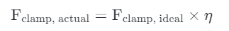
The efficiency ( η ) is typically represented as a fraction ( 0.75 ). In the case of normal, well-lubricated industrial toggle clamps, the mechanical efficiency(η) is between 0.60 and 0.85 Engineers must always use the lowest validated efficiency factor that a reputable manufacturer has provided, or, in the absence of such, a conservative estimate such as η= 0.65 may be used in preliminary calculations.
The geometric structure also influences the effective clamping force. For instance, in an edge clamp, the position of the clamping point relative to the pivot point of the clamping arm and the base drastically changes the amount of force delivered to the workpiece. The effective clamping force decreases as the clamping point moves away from the front of the base of the clamp towards the end of the clamp arm or the end of the bar. This highlights the importance of using the appropriate length of the standard clamping arm or, in cases where a special setup is used, considering an intermediate clamping point. The clamp’s essential features often dictate where the maximum force is generated.
The Actual Force of Your Pneumatic Clamp How to Calculate It
We will illustrate the whole process of an air-powered pneumatic toggle clamp that is more consistent than manual operation.
Scenario Parameters:
1. Target: A heavy assembly piece with the highest dislodging force of 2,000 N.
2. Safety Factor (SF): We select SF = 3.5 because of high repetition and wear possibilities.
3. Actual Force (F required): 2,000 N 3.5 = 7,000 N.
4. Chosen Clamp Model (Manufacturer Data):
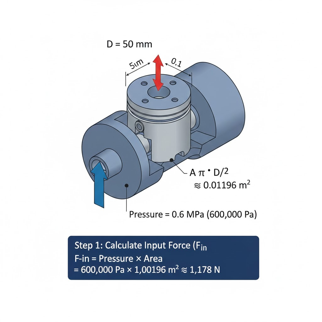
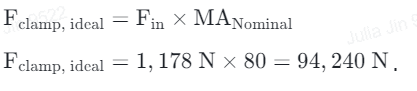
- Cylinder Piston Diameter: 50 mm.
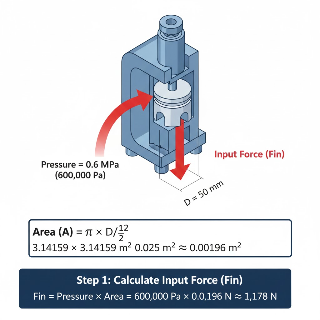
- Nominal Force Multiplication Factor (MA Nominal): 80.
- Maximum Air Pressure: 0.6 MPa (600,000 Pa).
- Tested Minimum Efficiency (η min): 0.75 (with a high-quality manufacturer such as Kunlong).
Step 1: Determine the Input Force (F in ) of the air cylinder.

Step 2: Determine the Theoretical Maximum (Ideal) Clamping Force (F clamp, ideal).
Step 3: Calculate the Actual Clamping Force (F clamp, actual) using the validated efficiency (η).

Conclusion: The real force exerted is 70,680 N. This clamp gives a comfortable margin of safety since the Required Actual Force was 7,000 N. In case, though, the necessary force was 75,000 N, this clamp would not be sufficient, which proves the need of such efficiency-adjusted calculation. This is done to make sure that the selected clamp is not only structurally rated but also functional to meet the requirements of the application.
The influence of Manufacturing Tolerances on Force Accuracy
Clamping force variability is not only a result of dynamic wear and friction, but also a result of the original manufacturing tolerances of the components. The quality of production is a filter to the ultimate performance reliability.
The fit of the pivot pins and holes in the links is critical to the integrity of the toggle linkage. When the tolerance of the pin diameter or the bore hole is too loose (excessive clearance) too much radial play is added. The play directly decreases the rigidity of the linkage, permitting greater flex and eliminating the ability of the mechanism to reach the desired over-center lock, thus greatly reducing the final force. On the other hand, too tight tolerances enhance friction. Quality manufacturing, then, is about obtaining an ideal fit that reduces play and friction.
Moreover, the formula of the clamping force is fully reliant on the precise lengths of the lever arms. Even a minor mistake (say, in the length of a link, especially of the ones near the spindle) in the length of a link can have a radical effect on the geometric multiplier, resulting in an unknown final force between one clamp and the next. Well-known manufacturers employ accuracy such as CNC machining to maintain the dimensions of links to very narrow tolerances so that the force multiplication factor remains the same in all units made. To give the customers the greatest assurance of this consistency, Kunlong supplements this consistency with a specialized and strict testing protocol that is intended to test and ensure the actual performance of the clamping force.
Kunlong Method: Assuring the Reliability of Clamping Force by means of Strict Testing
.webp)
Our Kunlong Method is our guarantee that accuracy is directly proportional to predictable, long-term clamping performance. We are concerned with reliability, and we start with a very experienced group of 30 engineers, who direct designs that are inherently robust.
Competitors are finding it difficult to cope with the unavoidable loss of force due to pin clearance and link length variances that are part of the manufacturing process, but Kunlong goes even further. We ensure unparalleled physical consistency by imposing a control over manufacturing error margins to an extreme of 0.0005 mm. This careful accuracy removes the geometric and frictional variability that destroys the accuracy of clamping forces.
To ensure long-term stability required by MRO experts, our clamps are thoroughly tested: a warranty of more than 20,000 cycles. Internal and third-party tests (SGS, RoHS) ensure environmental compliance, and more than 1000 hours of salt spray testing ensure the integrity of materials. This stratified quality assurance enables us to convert the estimated force calculations into a validated, measurable working asset.
Conclusion
The toggle clamp is a masterpiece in the amplification of forces, based on the beautiful simplicity of the four-bar linkage. But it can only be effective in any industrial application when its physics is clearly understood. The path between the theoretical ideal force and the real delivered force is characterized by the realities of friction, material deformation, and manufacturing tolerances.
The engineers should follow the principle that the only number that counts is the number of F clamp, actual. With the help of a strict safety factor, a conservative mechanical efficiency(η)or, more preferably, the efficiency factors that have been proven by the manufacturer (such as the ones obtained using the Kunlong Method), the accuracy and safety of the workpiece can be ensured. A rigorous method of force calculation turns the lowly toggle clamp into a holding device into a serious, measurable part of process control.
Faq
Q: What is the way to compute force without pressure?
A: Force may be determined without pressure by the ratio of Mass to Acceleration (F = ma), or by studying the torque/lever arm in mechanical systems, or by measuring the deflection of a known spring or load cell.
Q: What is the calculation of brake clamping force?
A: The force of braking is determined by multiplying the hydraulic line pressure by the total effective surface area of the caliper pistons:
Force = Pressure x Piston Area.
Q: What is the force of the clamp?
A: The real force is the Clamping Force (or working force), the force that can be used to act on the workpiece; it is usually less than the Holding Capacity stated by the manufacturer, because of friction and mechanical efficiency losses.