


The quest for rotational equilibrium in the strict environment of mechanical engineering is not just a whim but a structural requirement. Coupling alignment is the ultimate convergence of two or more shafts, whereby the centers of rotation are collinear under working conditions. This paper will give an analytical discussion of the geometric principles of shaft alignment, the procedures used to attain accuracy and the empirical implications of not observing these tolerances. Through the combination of technical information and industry best practices, we will develop a clear guideline for reliability engineers and maintenance practitioners. The goal is to move out of a condition of mechanical assembly to a state of optimized dynamic stability using a high-quality shaft coupling.
What is Coupling Alignment and Why It Matters
In its simplest form, coupling alignment is the procedure of aligning the spatial orientation of two coupled machines, usually a driver, like an electric motor, and a driven component, like a pump or compressor, in such a way that the centerlines of their shafts become one continuous line when they are operating. Although a system might seem in balance in a non-operative, static position, the application of torque, thermal expansion, and rotational inertia exposes the assembly to complicated vector forces that might not be aligned to the desired axis.
The importance of this process cannot be overestimated, both economically and mechanically. Adequate alignment serves as a protection against the parasitic tax of energy inefficiency. In the case of misalignment of shafts, some of the input energy is not used in producing useful work and is converted into heat and vibration. This not only raises the consumption of electricity but also hastens the entropy of the whole mechanical system. Within the framework of modern industrial optimization, accurate alignment is one of the main leverages to increase the Mean Time Between Failures (MTBF) and make sure that the lifecycle of the capital assets is as long as possible.
Identifying the Three Core Types of Shaft Misalignment
In order to successfully deal with the alignment errors, it is necessary to initially classify the geometric nature of the deviation. Misalignment in industrial rotating equipment is a multi-dimensional phenomenon that affects both flexible couplings and rigid gear couplings. It is generally classified into three main types:
Parallel Misalignment (Offset)
Parallel misalignment is where the centerlines of the two shafts are parallel to one another but are separated by a given distance, or offset. This deviation may be either horizontal or vertical. The coupling in this state is compelled to span a step-like gap, and this imposes asymmetrical loads on the internal elements of the coupling and the supporting bearings.
Angular Misalignment
Angular misalignment is defined as the centerlines of the shafts intersecting at a certain angle instead of creating a straight line. This gap is normally measured at the coupling faces. A microscopic angular deviation can result in a large amount of axial stress because the coupling has to flex or slide every time the shaft turns 360 degrees to fit the different distances between the shaft ends.
Axial Misalignment
The distance between the shaft ends (DBSE) is referred to as the axial misalignment. Although the majority of couplings are intended to accommodate a certain degree of axial “float,” when these limits are surpassed, thrust-loading of the bearings may occur. A skewed misalignment, a mixture of parallel and angular misalignment, is common in most instances, and a complex, multi-axis correction strategy is needed.
Proven Methods for Achieving Accurate Coupling Alignment
The development of alignment methodology is a continuation of the larger trend of industrial metrology, which has shifted to a digital accuracy of tactile observation.
Traditional Approaches: Straightedge and Feeler Gauges
The simplest but most common technique is the straightedge and feeler gauge technique. This method is based on the physical contact of a calibrated edge with the coupling hubs to measure parallel offset, and the gap between faces is measured using feeler gauges to measure angularity. Although this approach is cost-effective and does not need many setups, it is inherently constrained by human tactile sensitivity and the resolution of the instruments employed. It is typically inadequate in high-speed machinery where tolerances are in microns.
The Dial Indicator Technique: Rim and Face Methods
The dial indicator was a great improvement in mechanical accuracy. Technicians can get empirical data on the extent of misalignment by mounting an indicator on one shaft and rotating it against the rim and face of the other coupling hub. The Rim and Face method and the so-called Reverse Dial method enable the calculation of shim requirements and lateral adjustments using geometric formulas. Nevertheless, this technique is prone to bar sag, the physical deflection of the mounting hardware by gravity, which needs to be mathematically countered to achieve accuracy.
Modern Laser Alignment Systems
Laser alignment systems are the digital arbiter of mechanical veracity in the modern industrial setting. These systems make use of semiconductor laser diodes and position-sensing detectors to scan the coordinates of the shafts in real-time. The benefit of laser technology is that it removes human error in reading and automatically calculates the required movements at the machine’s feet. Complex variables like thermal growth and the presence of soft foot can also be considered by laser systems, and the repeatability of laser systems can be much greater than that of mechanical indicators.
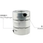
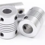
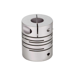
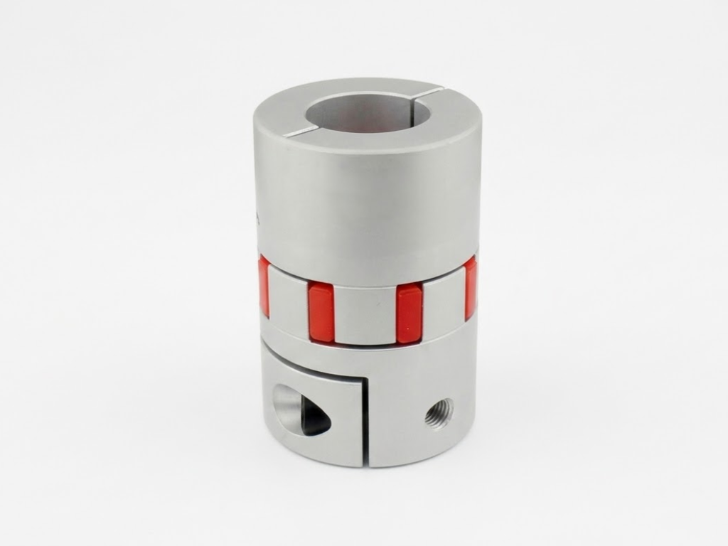
To supplement this measurement accuracy is the natural resilience of the coupling hardware itself. In most general-purpose applications, the elastomeric spider in a jaw connection is a vital mechanical buffer, offering a forgiving margin that accepts small residual misalignments that would otherwise be detected by manual equipment without damaging the shafts.
Practical Applications of Coupling Alignment
The use of alignment principles differs greatly from the profile of operation of the machinery. These nuances are necessary to understand how to adjust the alignment strategy to the unique needs of the environment.
In High-Speed Power Transmission, as in turbine-driven generators or high-speed centrifugal compressors, there is practically no room to spare. Even a small offset at speeds above 3,600 RPM causes enormous centrifugal forces that may cause instantaneous bearing failure. In this case, laser alignment and dynamic monitoring are obligatory.
In Precision Positioning Systems, on the other hand, such as CNC machinery and automated robotics, alignment is not so much about avoiding catastrophic failure, but rather about the fidelity of movement. A jaw coupling is often used in such situations, where the elastomeric element is able to absorb micro-vibrations. Nevertheless, the jaw coupling alignment should remain accurate to avoid backlash and to make sure that the encoder data is consistent with the actual output of the shaft.
Lastly, in Heavy-Duty Industrial Grids, like those used in mining or primary metal processing, alignment should consider structural deflection. Such large systems are prone to base-plate twist, in which the sheer weight of the equipment changes the alignment over time, requiring periodic checking.
Establishing Alignment Tolerances Based on Operating RPM
One of the most important myths in maintenance is that the manufacturer of the coupling determines the tolerance of the alignment. As a matter of fact, the tolerance is a variable of the rotational speed (RPM) of the shafts. The deviation that can be tolerated is exponentially decreasing with rotational frequency.
The table below summarizes the industry standards of what is considered to be an excellent alignment:
| RPM Range | Parallel Offset (mm) | Angularity (mm/100mm) |
| 0 – 1,000 | 0.13 | 0.06 |
| 1,000 – 2,000 | 0.08 | 0.05 |
| 2,000 – 3,000 | 0.05 | 0.03 |
| 3,000 – 4,000 | 0.03 | 0.02 |
| > 4,000 | 0.02 | 0.01 |
Adhering to these values ensures that the mechanical vibrations remain within the “Green Zone” of ISO 10816 standards, thereby preserving the integrity of the lubricant film within the bearings.
Why Misalignment Leads to Catastrophic Equipment Failure
The physics of stress distribution is the cause of misalignment and equipment failure. When the shafts are not collinear, the coupling must bend or slide to allow eccentricity. This cyclic loading produces heat- a symptom of energy loss but more devastating is the reaction load that is passed back to the bearings.
Misalignment is a pre-loading of the bearings and it has the effect of using a large percentage of the rated load capacity of the bearings before the machine even starts to work. This causes underground fatigue and subsequent spalling of the bearing races. Moreover, the resultant shaft wobble compromises mechanical seals, which are intended to work within tight radial clearances. When a seal breaks, the entry of contaminants or the loss of lubricant forms a feedback loop that causes the complete seizure of the rotating assembly.
Partner with KUNLONG to Optimize Coupling Solutions
At KUNLONG, we recognize that high-performance hardware is only as effective as its installation. Our engineering philosophy bridges the gap between precision manufacturing and rigorous maintenance standards to ensure operational excellence.
KUNLONG couplings and jaw couplings are engineered to achieve an optimal balance between torque capacity and misalignment compensation. By utilizing advanced CNC machining, we maintain a precise tolerance range of 0.0005mm. This extreme accuracy minimizes the “built-in” concentricity errors common in lower-tier components, allowing your technicians to achieve perfect coupling alignment faster and with greater repeatability.
Our commitment to reliability is backed by a team of 30 expert engineers and a rigorous 15-point quality inspection for every batch. From ISO9001 certified processes to materials that withstand extreme temperatures, KUNLONG components are built for high-load industrial environments. By integrating our precision-engineered solutions, you are not just purchasing a part; you are reducing the Total Cost of Ownership (TCO) through enhanced system stability and extended service life.
A Comprehensive Checklist for a Successful Alignment Procedure
In order to achieve a successful and repeatable alignment result, KUNLONG suggests the following strict procedure:
- Pre-Alignment Inspection: Wipe all mating surfaces. Ensure that the shaft and keyway are not burred or deformed.
- Soft Foot Correction: Make sure that the four feet of the machine are on the same plane. The frame will be distorted by a soft foot condition, making it impossible to align the bolts.
- Thermal Growth Estimation: Consider vertical growth of the motor as it attains operating temperature.
- Preliminary Rough Alignment: A straightedge is used to bring the system into the range of precision tools that can be measured.
- Precision Measurement: Measure horizontal and vertical deviations using a laser system or dial indicators.
- Adjustment: Shim the machine horizontally and move it vertically. Bolts should always be tightened in a star shape to ensure that the pressure is even.
- Final Check: Check- Check of the machine by a hot check, where feasible, again measuring the alignment once the machine has stabilized at steady-state temperature.
Conclusion
Mechanical reliability is an ongoing process of seeking perfect coupling alignment. Knowing the geometric types of misalignment and using the right metrological instruments, including simple indicators and advanced laser systems, the industrial processes can reduce the risk of early component failure to a considerable extent. This paper has outlined the structural and economic necessities that render precision alignment an indisputable element of contemporary maintenance. The principles of rotational collinearity are the same whether it is a high-speed turbine or a precision CNC axis. By combining strict compliance with procedures and the choice of high-performance equipment among the partners, such as KUNLONG, engineers will be able to guarantee the long-term stability and efficiency of their industrial resources.