


Introduction
The coupling is often considered a secondary element in the complicated design of industrial power transmission, a mere bridge between a prime mover and a driven load. Nevertheless, this view ignores a basic fact of mechanical engineering: the mechanical fuse of the system is the coupling. It does not just pass on torque, but must absorb the inevitable misalignments, absorb vibrations, and cushion against the disastrous effects of such expensive machinery as motors and gearboxes.
A failed coupling has far reaching implications that go beyond the price of the replacement component. The actual effect is quantified in non-planned downtime, labor expenses, and possible secondary damage to shafts and bearings. To keep the operational efficiency, engineers and maintenance professionals should not be in a reactive mode of thinking of fixing it when it breaks but rather in a strict knowledge of why these components fail and how to interpret the physical evidence they leave behind. This guide offers a detailed technical discussion of the failure of coupling, starting with the causes of the failure, up to the forensic identification and prevention of the failure in the long term.
Root Cause Analysis: Why Do Couplings Fail Prematurely
The solution to a failure requires one to comprehend the cause of the failure. Couplings are constructed to last a certain amount of time under rated conditions; early failure is nearly always an indicator of external stress or human error.
Misalignment
Misalignment is the primary cause of coupling failure, accounting for an estimated 50% to 70% of all recorded incidents in rotating equipment. It is the robber of mechanical energy, the silent robber, which takes away the force and directs it to destructive heat and vibration instead of productive work. Misalignment can be generally of three types:
- Parallel (Offset) Misalignment: The shafts are parallel but the centerlines do not align. This causes the coupling to bend twice in a revolution, which causes quick fatigue.
- Angular Misalignment: The shafts cross at an angle. This causes an asymmetric loading of the internal components of the coupling (the spider of a jaw coupling or the shim packs of a disc coupling).
- Axial Misalignment: Shafts are either forced together or forced apart beyond the end-float capacity of the coupling.
At misalignment beyond the tolerances of the manufacturer, the coupling produces reactive forces which are reflected back to the bearings. This raises the operating temperature and reduces the life of the whole drive train.
Torque Overload & Peak Load Shocks
Each coupling has a nominal torque (Tn) and a peak torque (T$). When the application requirements surpass these limits, failure will occur.
- Instantaneous Overload: An abrupt jam or emergency stop produces a torque spike that is greater than the yield strength of the material. This normally causes a clean brittle fracture of the hub or the shearing off of the elastomer immediately.
- Peak Load Shocks: Cyclic fatigue is caused by repeated high torque cycles such as those found in crushers or reciprocating pumps. With time, the metallic or elastomeric components develop microscopic cracks, which ultimately cause a failure at torque levels that are much lower than the original rating.
Lubrication Issues
Although modern jaw and disc couplings are frequently lubrication-free, gear and grid couplings rely completely on high-quality grease to reduce friction between moving metallic components.
Lubrication failure is by centrifugal separation, in which the high speed of the coupling causes the heavy base oil to be thrown out of the thickener, leaving a dry abrasive paste in the gear teeth. Moreover, when seals are broken, water or dust contamination will convert the lubricant into a grinding compound. In the absence of an adequate lubricating film, the metallic teeth experience “fretting” and “galling” and the material is lost quickly and the entire mechanism fails.
Environmental Stress
The load itself may be as destructive as the environment in which a coupling is used.
- Temperature extremes: Elastomeric spiders can be made to soften and lose their load-bearing ability by high ambient heat, which increases the rate of their hysteresis. On the other hand, very low temperatures may cause materials to be brittle.
- Chemical Exposure: Washdown procedures in food processing or chemical plants may include acidic or alkaline cleaners. When the coupling material is not chemically compatible (e.g. using standard nitrile rubber when urethane is needed), the material will swell, crack or dissolve.
- Contamination: Abrasive dust in mining or cement industries may penetrate the coupling, which is an unwanted abrasive that erodes contact surfaces.
Improper Selection
The failure usually starts in the procurement office and not in the factory floor. When the Service Factor is not taken into consideration, improper selection takes place. As an example, a coupling with a steady-state electric motor rating will not last long when used on a high-vibration diesel engine without re-rating it to accommodate the higher shock loads. When a coupling is undersized to reduce the initial capital expenditure (CAPEX), the maintenance costs (OPEX) will always be more than the savings.
Installation Errors
Even the best quality coupling cannot withstand bad installation. Common errors include:
- Wrong FastenerTorque: Under-torqued hub bolts may vibrate loose, over-torqued may exceed their proof load and break.
- Keyway Problems: An ill-fitting key will cause a point load on the shaft that may cause shearing of the shaft or cracking of the hub.
- Gap (DBSE): The inability to establish the proper distance between the ends of the shafts (DBSE) causes the coupling to be unable to accommodate the axial movement, causing the thrust loading on the motor bearings.
Early Warning Signs: Identifying Failures Before They Happen

A coupling that is about to become fully fractured tends to give a number of sensory and operational signals:
- Abnormal Noise: Squealing noises of high pitch usually denote metal-to-metal contact because of the loss of lubrication. Rhythmic thumping or clicking is normally indicative of extreme misalignment or loose hub.
- Excessive Vibration: A simple handheld vibration pen can be used to detect levels that are beyond ISO 10816. The physical manifestation of the coupling struggling against misalignment is vibration.
- Heat Generation: Excessive heat in elastomeric couplings is an indication of internal friction (hysteresis). When the coupling hub is too hot to touch, then it is probable that the misalignment is pushing the elastomer to operate outside of its thermal limits.
- Abnormal Shaft Movement: Obvious axial or radial play indicates that the coupling is no longer able to hold the shaft centred, and may cause damage to the bearings of the motor or gearbox.
- Visual Damage: The hub or shims may have cracks in the hairline, or metal discoloration (blue or straw tinting) due to long-term overheating.
- Debris: Black rubber dust or metallic shavings under the coupling guard is a sure indication of active wear.
- Performance Fluctuations (Backlash): In 3C automation and precision robotics, torsional rigidity decreases, causing backlash to increase. This is in the form of positioning drift and loss of accuracy in high speed assembly processes.
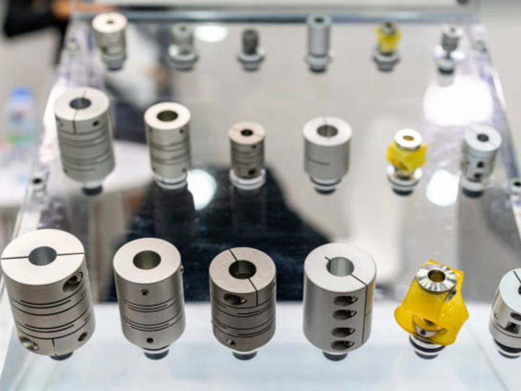
Forensic Analysis: Failure Modes Across Different Types
Forensic analysis is the autopsy of a failed process. By examining the remains, we can deduce the cause of death.
| Coupling Type | Critical Wear Component | Typical Failure Mode | Forensic Evidence (Visual Clues) |
| Jaw (Elastomeric) | Spider (Elastomer) | Compression Set / Shearing | Flattened petals, brittle fragments, or rubber dust. |
| Disc (Metallic) | Shim / Disc Pack | Fatigue Cracking / Buckling | Bolt-hole cracks, warped shims, or reddish fretting dust. |
| Bellows | Thin-walled Tube | Work-hardening / Torsional Twist | Convolution cracks or spiral tube deformation. |
| Oldham | Center Slider (Acetal/PEEK) | Abrasive Wear / Thermal Melting | Deep slider grooves, thinning, or thermal melting. |
| Gear | Internal/External Teeth | Pitting / Scuffing / Galling | Pitted tooth flanks or dry lubricant sludge. |
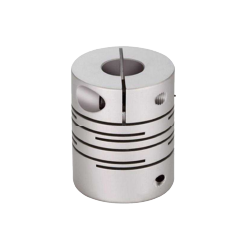
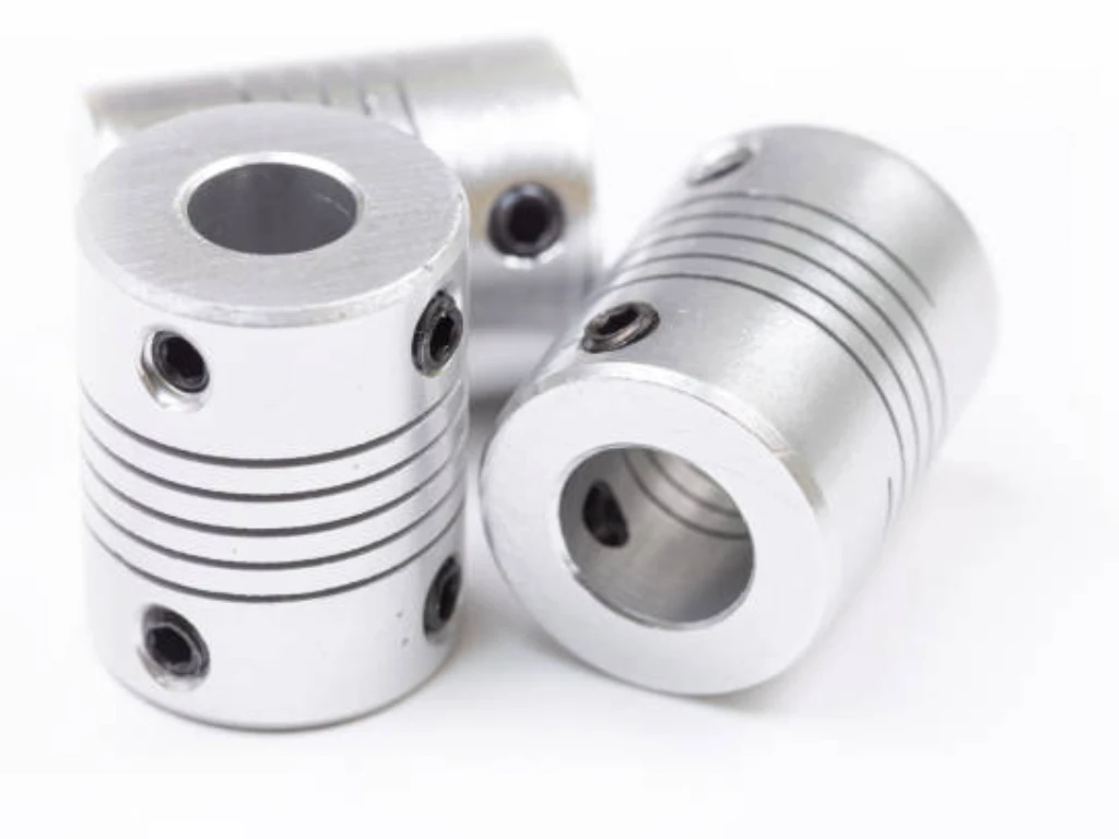
| Beam (Helical) | Integrated Slotted Beam | Fatigue Fracture | Complete snap or permanent axial elongation. |
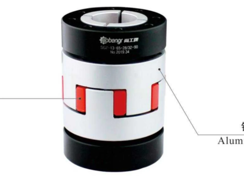
Jaw Couplings
The main wear component in a jaw coupling is the spider (elastomer).
- Compression Set: When the spider appears flatter or thinner than a new one, it has been subjected to constant overload or excessive heat.
- Spider Shearing: When the legs of the spider were neatly cut off, an instantaneous torque spike (jam) was observed.
- HubEar Fracture: When the metallic jaws of the hub fracture, it is typically a result of both extreme misalignment and fatigue, or the utilization of a hub material (such as cast iron) that was too brittle to handle high-shock loads.
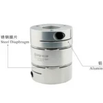
Disc Couplings
Disc couplings are based on thin stainless steel shims.
- Shim Cracking: Cracks on the bolt holes are signs of angular misalignment. The shims are being bent to and fro beyond their elasticity.
- Buckling: When the shims appear distorted or wavy, the shafts have probably moved in an axial direction, forcing the shim pack out of its design envelope.
Gear Couplings
Gear couplings make use of the mechanical interlocking of internal and external teeth, and depend greatly on a uniform film of lubricant to inhibit metal-on-metal wear.
- Pitting and Scoring: Small pits on the tooth surface denote the absence of lubrication or polluted grease.
- Broken Teeth: This is a definite indication of excessive torque overload or extreme misalignment of the offset that resulted in the teeth bottoming out.
Bellows Couplings
Bellows couplings are engineered to be zero-backlash and high torsional stiffness, and are therefore sensitive to over-displacement.
- Fatigue Cracking: The most typical failure indication is cracks in the convolutions (the bellows folds). This means that the coupling was either angularly or parallel misaligned beyond its rated limits, which led to the work-hardening of the thin metal and subsequent fracture.
- Torsional Deformation (Spiral Twist): When the bellows is observed to be twisted or spiraled, it has undergone a torque spike that surpassed the material yield strength, usually due to an abrupt mechanical jam or emergency stop in high-speed servo systems.
Oldham Couplings
The Oldham coupling is a three-piece design that has a sliding center disk to allow parallel misalignment.
- Center Disk Abrasion: When the center slider (typically of Acetal or PEEK) exhibits deep grooves, thinning, or melting, it is a sign of excessive parallel misalignment. The heat produced by the continuous movement under load causes degradation of the polymer.
- Tenon/Slot Fracture: When the bulging “tenons” on the hubs are sheared off, or the slots in the disk are sheared off, the cause is usually an instantaneous overload of the torque that was greater than the shear strength of the center element.
Troubleshooting & Diagnosis: From Visual Inspection to Vibration Analysis
A coupling problem diagnosis needs a tiered approach that progresses through external observation to internal data analysis. This is basically a forensic search of the “Root Cause” that has been identified above.
- Level 1: Qualitative Sensory Inspection. This is the initial line of defense. Technicians are to observe the coupling guard in case of abnormal debris, hear the rhythmic clicking of a loose hub, and infrared thermography to identify local heat accumulation. Although this level is cost-effective, it only detects symptoms, not causes.
- Level 2: Geometric Verification. Once a symptom has been identified, the equipment should be locked out to conduct a static measurement. Radial and axial run-out can be checked using dial indicators to determine whether a change in the foundation of the machine or soft foot has taken place. This step identifies whether the physical geometry of the drive train has violated the limits of the coupling.
- Level 3: Predictive Vibration Analysis. Vibration analysis is the most advanced diagnostic tool that analyzes the signature of the machine. Through frequency analysis, an expert can isolate certain defects: a peak at 1X rpm is usually indicative of a bent shaft, and a predominant 2X vibration frequency is a typical sign of misalignment. This enables planned intervention before a disastrous fracture takes place.
Prevention Through Precision: Best Practices for Maintenance
To avoid failure, accuracy should be shifted to a diagnostic activity to a maintenance culture. Prevention is not fault-finding, it is creating a condition in which they do not take place.
- Standardized Laser Alignment. Give up the subjectivity of straightedges. The current maintenance demands laser alignment systems with accuracy of 0.01mm. The reactive forces on the coupling are reduced to a minimum by making sure that the shafts are perfectly collinear when initially installed and after each major service, which exponentially increases the life of the elastomer or metallic shims.
- Calibrated Torque Compliance. One of the causes of hub slip is fastener failure. The maintenance procedures should require the application of calibrated torque wrenches on all bolts. A cross-pattern tightening sequence will provide even distribution of the clamping force of the hub around the shaft to avoid the point loading that causes fractures.
- Lubrication Cycles that are engineered. In the case of gear and grid couplings, a lubrication schedule is a crucial operational parameter. High-centrifugal-force (HCG) grease is used to avoid the separation of the thickener and base oil. Prevention does not only entail the addition of grease, but also the removal of old and contaminated lubricant to keep the hydraulic film between meshing teeth.
- Strategic Environmental Shielding. When acidic washdowns or abrasive grit are involved in the application, the standard coupling guard cannot be used. To prevent, it is necessary to upgrade to 316-grade stainless steel parts or use non-contact labyrinth seals to separate the coupling with the destructive parts of the facility.
The “50% Rule”: When to Repair vs. Replace
The 50% Rule is a decision-making rule in the economic management of industrial assets. When the cost of repairing a coupling, the labor, the parts, and the opportunity cost of the lost time is more than half the cost of a new, better quality unit, then replacement is the logically better option.
Replacing a badly worn, worn out coupling is usually just a way of resetting the clock on a damaged system. Substituting it with a new, high-tech, precision-engineered version, usually recovers the cost in the first year of service in terms of less maintenance and repairing labor.
How Kunlong Eliminates Coupling Failure at the Source
At Kunlong, we view coupling manufacturing not as a commodity trade, but as a discipline of precision engineering. We understand that most system failures are preventable through superior material science and rigorous manufacturing standards.
As a one-stop industrial hardware provider, we integrate 100% quality control into every stage of production. By achieving precision tolerances as tight as 0.0005mm, we reduce the minute inconsistencies that lead to vibration and premature wear. Our commitment to reliability is backed by SGS and ROHS certified materials, offering exceptional corrosion resistance and the high load-bearing capacity required for heavy-duty industrial environments.
We don’t just supply parts; we provide solutions. Our team offers professional selection guidance and custom design services tailored to your specific operational needs. By combining technical expertise with high-performance materials, Kunlong transforms the coupling from a potential weak link into a reliable asset for long-term industrial stability.
Conclusion
Coupling failure is rarely an accident; it is the predictable outcome of mechanical stress, environmental challenge, or human oversight. By treating the coupling as a critical diagnostic tool—analyzing its warning signs and performing forensic audits on failed parts—maintenance professionals can transition from a state of constant firefighting to one of controlled, predictable productivity.
Ultimately, the goal of any waterfront or industrial operation is reliability. When you prioritize precision alignment, correct selection, and high-quality components like those from Kunlong, you are not just preventing a part from breaking; you are securing the long-term health of your entire mechanical infrastructure. If you are currently facing recurring failures, now is the time to apply the 50% rule and upgrade to a system designed to eliminate failure at its source.