


Introduction
The contemporary industrial environment is defined by an unseen but thick congestion: the electromagnetic spectrum. With the spread of electronic devices, such as cellular networks, 5G communication towers and high-precision medical equipment, the electromagnetic environment is becoming more and more noisy. In this respect, Electromagnetic Interference (EMI)—and its specific type of interference known as Radio Frequency Interference (RFI)— is a major inefficiency, a systemic failure in which an external source interferes with the internal balance of a device, or vice versa, a device that pollutes its environment.
The solution to this inefficiency is the EMI shielded enclosure. It is not just a box; it is a boundary condition that is meant to separate a system out of the electromagnetic anarchy of the external world. The design of such an enclosure is an optimization. Engineers have to trade high electrical conductivity and cost, structural rigidity and weight, and sealing integrity and accessibility. This manual examines the mechanical principles of effective shielding, the legal requirements that have led to its necessity, and the importance of high-accuracy hardware in ensuring the effectiveness of the system.
.webp)
What is an EMI Shielded Enclosure?
Essentially, an EMI shielded enclosure(often functioning as an RFI shield) is a conductive shield that surrounds an electronic circuit. Its main role is to reduce the strength of the electromagnetic field to a level that is acceptable by the working conditions of the device. This is done by the physical laws of the Faraday cage, in which an external static electrical field is used to cause the electric charges in the conductive material of the enclosure to be distributed in a way that cancels the effect of the field inside the enclosure.
While traditional metal enclosures have served this purpose for decades, modern demands require addressing a vast range of frequencies across the radio frequency spectrum. But in dynamic industrial use the mechanism is more complicated than simple cancellation. There are three different mechanisms of shielding to attenuate electromagnetic energy:
- Reflection: The main process of protecting electric fields (E-fields). When an electromagnetic wave is incident on a conductive surface, some of it is reflected off, similar to light on a mirror.
- Absorption: When the wave enters the shield material, it is absorbed as heat because of ohmic losses in the metal. This is essential to magnetic fields (H-fields) and high-frequency plane waves.
- Multiple Reflections: Reflections or partial absorptions of the waves that are not reflected or completely absorbed can occur between the internal surfaces of the boundaries of the shield material. This process offers extra attenuation especially in thin shields that have high surface areas.
An enclosure designed well provides an isolated environment, so that the internal electronics will only receive the signals it is intended to, and not the stochastic noise of the external environment.
Important Regulatory Standards and Compliance of EMI Shielded Enclosures
In the international market, Electromagnetic Compatibility (EMC) standards are not a choice; they are a requirement before entry to the market. These laws act as a tax on inefficiency, punishing manufacturers whose devices produce too much noise or cannot work in normal electromagnetic conditions.
- Federal Communications Commission (FCC) – United States: In the case of the North American market, the statute that applies is FCC Part 15. It separates Class A (industrial/commercial) and Class B (residential) devices. Class B standards are much more stringent and demand greater shielding effectiveness (SE) since residential settings do not have the controlled separation of industrial areas. Any failure to comply with these emission limits leads to a ban on sales.
- Conformite Europeenne (CE) – European Union: The EMC Directive (2014/30/EU) of the EU demands a declaration of conformity. The CE marking involves strict immunity testing as opposed to the FCC which pays much attention to the emissions. The enclosure should demonstrate that it can resist external interference without failure. This bilateral need frequently requires stronger shielding designs than those designed exclusively to meet the US market.
- MIL-STD-461- Military and Defense: The United States Military Standard provides the strictest set of requirements. It determines the management of electromagnetic interference emissions and susceptibility of military equipment. The enclosures used in this industry may need 80dB to 100dB of attenuation, which may demand high-quality materials and smooth construction that is well beyond the capabilities of consumer-grade products.
Typical EMI Enclosures by Form Factor
The size of the electronics contained in an enclosure and the conditions under which it will be used determine the physical geometry of the enclosure. These can be divided into four main form factors.
PCB Level Shields (Board Level) These are tiny metal cans that are soldered directly to the printed circuit board. They shield certain noisy circuits (such as processors) or delicate circuits (such as RF receivers). Although they are cost-effective in localized shielding, they fail to shield the device against external environmental risks.
- Desktop and Rack-Mount Enclosures: These enclosures are used in telecommunications and server rooms and fit standard 19-inch racks. They are based on conductive gaskets and special ventilation panels. The structural integrity in this case is critical because the chassis is the system ground.
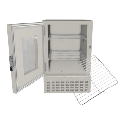
- NEMA/IP Rated Industrial Cabinets: These are large, free standing enclosures that are utilized in factory automation and power generation. They should offer EMI shielding and at the same time offer protection against dust and water (IP65/IP66). This two-fold need makes the design more difficult because the conductive gaskets employed in EMI are not usually the same as the elastomeric gaskets employed in waterproofing.
- Shielded Rooms and Anechoic Chambers: These are the macro scale of shielding. Conductive material (usually copper or galvanized steel) is used to line entire rooms to provide a testing environment that is free of ambient RF noise. These play a vital role in the R&D stage of electronic products development.
.webp)
Designing EMI Shielding: Critical Design
The problem of designing an effective EMI shield is a multivariate problem. The engineer cannot just maximize the wall thickness without weight, cost and thermal management. The variables that follow should be balanced to attain the required Shielding Effectiveness (SE).
Choosing the appropriate Material
The material determines the potential of the shield. It is a trade-off between electromagnetic performance, which is determined by conductivity (reflection) and permeability (absorption), and physical realities. In addition to these, mechanical suitability (yield strength), density (weight constraints), manufacturability and cost are also to be considered by engineers to make sure that the enclosure is structurally sound and commercially viable.
| Material Class | Key Traits | Conductivity (% IACS) | Permeability (μr) | Density (g/cm3) | Mechanical Suitability (Yield Strength) | Manufacturability | Cost | Best Applications |
| Copper | Benchmark conductivity; Excellent reflection | 100% | ~1.0 (Non-magnetic) | 8.96 | Low-Medium (~70-200 MPa) Soft | Medium (Solderable, gummy to machine) | High | MRI rooms, RF shielding, precision instruments |
| Aluminum (6061/5052) | Lightweight; Oxide layer requires treatment | ~40% – 45% (Alloy) Pure Al is 61% | ~1.0 (Non-magnetic) | 2.7 | Medium (~90-270 MPa) High strength-to-weight | High (Extrusion, stamping, CNC) | Medium | Aerospace, telecom housings, electronics |
| Galvanized Steel | Rigid; Good magnetic attenuation | ~10% – 15% | ~300 – 1,000 (Low Freq) | 7.85 | High (~250-400 MPa) Structural integrity | High (Weldable, bendable) | Low | Server racks, industrial cabinets |
| Mu-Metal | Ultra-high permeability; Stress-sensitive | ~3% | ~20k – 100k (Max) | 8.7 | Low (~150 MPa) Very soft | Low (Requires annealing) | Very High | Transformers, magnetic shielding |
| Conductive Plastics | Moldable; Lightweight | < 1% | ~1.0 | 1.2-1.5 | Low-Medium (~30-60 MPa) Brittle | High (Injection molding) | Med-High | Handheld devices, complex shapes |
| Stainless Steel (304/316) | Corrosion-resistant; Durable | ~2% – 3% | ~1.008 (Non-magnetic) | 7.9-8.0 | Very High (~215-500+ MPa) Durable | Medium (Work hardens) | Med-High | Marine, outdoor, food processing |
Computation of Shielding Effectiveness and Thickness
The Shielding Effectiveness (SE) is expressed in decibels (dB) in a logarithmic form. It is the ratio of the field strength in the presence of the shield and the field strength in the absence of the shield. SE = A + R + B: Absorption Loss (A), Reflection Loss (R), and Multiple Reflection Correction Factor (B):
SEdB=A+R+B
Absorption Loss (A) depends on the thickness of the shield and the skin depth of the material. Current is confined to the skin of the conductor at high frequencies. The higher the frequency, the lower the skin depth. Thus, even thin foils of conductive material are adequate in high-frequency interference (GHz range). But at low frequencies (kHz) absorption is the only important process, and requires thick, high-permeability materials such as steel or Mu-metal.
To find out the minimum thickness, the engineer has to compute the “Skin Depth” ( δ ). When the thickness of the material is smaller than a skin depth, the shielding will be damaged.
Dealing with Ventilation and Apertures
An ideal Faraday cage is one that is not open. As a matter of fact, enclosures require cooling, cabling, and display holes. These holes serve as slot antennas; when the length of the slot is close to a quarter-wavelength ( λ/4 ) of the interference frequency, the shield becomes transparent to that frequency, effectively leaking energy.
To counter this, the principle of Waveguide Beyond Cutoff is used. We can cut off frequencies below a certain cutoff by considering a vent hole as a waveguide tube instead of a 2D hole. This is commonly done with honeycomb filters, in which the depth of the honeycomb cell is many times its diameter, permitting air to pass but excluding electromagnetic waves.
.webp)
The “Secret” Weakness: Why EMI Shielding is so Frequently Unsuccessful
Although theoretical computations tend to use a smooth sphere of conductive substance, the fact of production presents discontinuity. Most EMI enclosures have a weakness that is not the sheet metal, but the interfaces, the seams, the doors, and the access panels.
The mating surfaces are the main points of leakage. When a door is not closing with equal pressure, gaps are created. Shielding at high frequencies can be compromised by even a microscopic gap. Moreover, the performance is worsened by environmental factors in the long run. Galvanic corrosion, which occurs when dissimilar metals are brought into contact (e.g. an aluminum enclosure with a steel gasket) in the presence of moisture, forms an insulating oxide layer. This enhances contact resistance, disrupting the electrical continuity needed by the shield to operate.
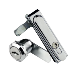
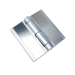
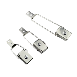
The other failure mode is the compression set of shielding gaskets. Poor-quality gaskets lose elasticity with time. Unless the enclosure hardware (latches and hinges) can hold a constant, high-pressure force, the gasket will not rebound, providing a leakage path. Therefore, the mechanical hardware is not just an accessory; it is a very important part of the electrical circuit. The most economical method of providing long-term EMI compliance is therefore the selection of the appropriate latching and hinging mechanisms.
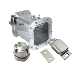
Sealing Integrity Optimization with KUNLONG Professional Industrial Hardware
The mechanical integrity of an enclosure is often the deciding factor in maintaining long-term EMI compliance. KUNLONG secures this integrity by delivering industrial hardware that combines rigorous engineering with manufacturing precision. Backed by 108 patents and a team of 30 experts with a decade of industry experience, we have developed over 150 advanced proprietary solutions to solve complex sealing challenges that standard parts cannot.
Our hardware is engineered to eliminate RF leakage gaps, with error margins controlled to an ultra-precise 0.0005mm. To ensure consistent conductivity and prevent oxidation—a common cause of shielding failure—our products meet a 1,000+ hour salt spray standard. This reliability is enforced through a full-process QC system where every batch undergoes 15 strict inspections to guarantee a 20,000+ cycle lifespan. Certified by ISO9001, ROHS, and CE, KUNLONG delivers the robust hardware necessary to secure your enclosure’s performance.
EMI Enclosure Critical Applications and Hardware Requirements
Although the basic principle of EMI shielding, which is to provide a conductive barrier to prevent electromagnetic interference, is universal, the engineering limitations are quite different in different industries. A case that is Medical device applications (like MRI) face different challenges than aerospace applications exposed to vibration.
Therefore, the performance of an EMI enclosure does not only depend on the shielding material, but on the mechanical integrity of the assembly to these particular stresses. The table below describes how the main sectors respond to the specific operational conditions, such as thermal cycling and space restrictions, and how the robust hardware is essential to ensure the long-term compliance.
| Industry Sector | Primary Challenge | Critical Hardware Solution |
| Test Chambers | Thermal Cycling (Extreme expansion/contraction) | Constant Compression to maintain seal integrity |
| 5G / Telecom | Outdoor Corrosion (Rust breaks conductivity) | Stainless Steel (IP66) to preserve grounding path |
| Medical (MRI) | Zero Signal Leakage (High sensitivity) | Ultra-Precision (<0.0005mm) & Non-Magnetic materials |
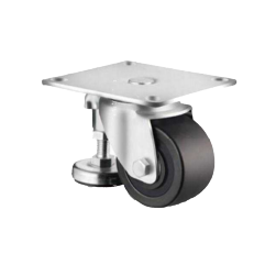
| Automation | Heavy Vibration (Risk of loosening) | Vibration-Proof latches to prevent contact failure |
| New Energy (EV) | Space Constraints (Tight installation) | Compact, Multi-Point systems for high strength in small spaces |
Conclusion
EMI shielded enclosure design is a complicated formula that incorporates electromagnetic theory, material science, and mechanical engineering. It involves a holistic approach in which the metal sheet, the conductive gasket, and the closing mechanism are considered as one continuous electrical conductor.
Although the choice of the base material, such as copper, aluminum, or steel, defines the theoretical maximum of shielding effectiveness, the actual performance is nearly always limited by the mechanical integrity of the seams and apertures. Here, the accuracy of manufacturing and quality of materials of components of experts such as KUNLONG comes in handy. The lock which keeps the door closed is as important in the balance of electromagnetic compatibility as the wall which keeps the wave out.
Faq
Q: What is EMI shielding?
A: To prevent the entry or exit of undesired electromagnetic signals into or out of a device, to maintain a stable performance and meet EMC standards.
Q: What is the purpose of a shielded chamber in EMI testing?
A: It provides a noise-free environment to allow engineers to measure emissions and immunity accurately without the external noise influencing the results.
Q: What are the symptoms of EMI?
A: Signs are common such as loss of signal, flickering display, noisy audio, communication drop, data errors, unintended resets or malfunction of the device.
Q: What is the shielding effect?
A: With conductive materials that absorb or reflect electromagnetic waves, minimizing incoming and outgoing interference.