


Introduction
In the harsh environment of industrial machinery and heavy-duty mechanical power transmission, the transfer of high torque between two rotating shafts is hardly a question of a simple, linear relationship. Torque transmission is physically subject to physical variables, such as thermal expansion, structural deflection, and manufacturing tolerances, which render ideal precise alignment an unrealistic ideal.
The industrial drive train is a sensitive ecosystem where any microscopic variation may cause system failure unless it is well controlled. It is here that flexible coupling is an essential element. The flexible coupling is much more than a connector, the complex interface that allows the flow of power and allows the imperfections of the physical world to be accommodated. The different types of flexible coupling are varied and it is important for any engineer or operator to understand the various types of flexible coupling to maximize the longevity and reliable operation of their equipment.
What is a Flexible Coupling
In order to define a flexible coupling, it is necessary to identify the difference between it and a rigid one. Whereas a rigid coupling forms an indestructible bond between two shafts, which must be almost perfectly collinear, a flexible shaft coupling is made to allow a calculated amount of relative motion. In particular, it is a mechanical mechanism that is employed to join the ends of two shafts to transmit power at a constant rotational rate, and at the same time, correct misalignment and absorb shock.
Kinematically, a flexible coupling adds degrees of freedom to a drivetrain. These devices can be used to transmit the torque without causing excessive reaction forces on the bearings of the motor or the driven equipment by either the elastic deformation of materials or the strategic clearance between mechanical components. These couplings are not weak in structure but are rather a very carefully designed reaction to rotational stresses. The flexible coupling takes care of the geometric reality of the assembly, whether it is a polyurethane spider in a jaw coupling or the stainless steel leaves of a disc pack, to ensure that the components do not prematurely fatigue.

Core Functions: Beyond Just Joining Two Shafts
The usefulness of a flexible coupling is multi-dimensional, as it solves a number of significant engineering issues in one unit. Although the main task is to transmit torque, the secondary functions determine the reliable performance of the whole mechanical system.
Misalignment Compensation
The three main types of shaft misalignment that a flexible coupling can address are:
- Parallel (Offset) Misalignment: The axes of the two shafts are parallel, but not on the same straight line.
- Angular Misalignment: This occurs when the shafts are not parallel to each other, affecting the transmission of rotary motion.
- Axial Displacement: As the shafts move either towards or away, usually as a result of thermal expansion or hydraulic thrust.
The flexible coupling is a mechanical fuse, which sacrifices its own wear parts, or uses its own elasticity to absorb the bending moments of these offsets on the more costly shafts and bearings.
Vibration Dampening and Shock Absorption
Non-linear loads or harmonic resonances are common in mechanical systems. To illustrate, a motor that is used to power a reciprocating compressor will have periodic torque spikes. Flexible couplings, especially those that make use of elastomeric components, are dampeners. They absorb kinetic energy by means of internal molecular friction (hysteresis), so that high-frequency vibrations do not propagate between the driven load and the motor, or the other way round. This minimizes the mechanical noise and eliminates the chatter that may damage precision components such as encoders.
Torsional Tuning and Protection
The natural frequency of the drive train is tuned using the coupling in some high-speed or high-precision applications. The engineers can shift the resonant frequency of the system out of the operating speed range by choosing a coupling with a desired torsional stiffness and high torque capacity, thus preventing disastrous vibration. Moreover, when a jam or overload occurs suddenly, numerous flexible couplings are constructed to fail safely, breaking the drive and preventing the motor from experiencing an immediate burst of torque.
Categorizing Flexible Coupling Types: Material Flex vs. Mechanical Flex
The large market of flexible coupling types can be categorized in a systematic way into two broad philosophies of design: Material Flexing and Mechanical Flexing.
Material Flexing Couplings
Material flexing couplings are based on the physical deformation of the components to provide operational flexibility. These elements are usually composed of elastomers (e.g., natural rubber, nitrile, or polyurethane) or fine metallic parts (e.g,. stainless steel or spring steel).
Material flexing designs are characterized by the fact that they usually do not contain any moving parts. Since the compensation of misalignment does not involve any metal-on-metal contact or sliding, these couplings do not need to be lubricated. They are commonly referred to as maintenance-free since the fatigue limit of the material is used to determine their service life as opposed to mechanical wear. They are best suited to clean environments, high-speed applications with zero backlash, and where accessibility to maintenance is restricted.
Mechanical Flexing Couplings
Mechanical flexing couplings, on the other hand, attain flexibility through the tactical clearance between interlocking components. These components slide, roll, or pivot over each other to allow deviations in shafts. Since such designs require the movement of surfaces, they nearly always need periodic lubrication (grease or oil) to reduce friction and eliminate galling.
The main benefit of mechanical flexing couplings is the torque density. Since they are based on the structural strength of steel-on-steel contact, they are able to transmit much higher torque in a smaller physical footprint than elastomeric types. They are used in heavy industrial applications, where the loads are extreme and the environment may be harsh, e.g., mining, steel production, and large-scale pumping.
Deep Dive: Popular Flexible Coupling Types and Their Applications
In order to choose the right component, it is necessary to take a closer look at the particular features of the most widespread types of flexible couplings that are used in the modern industry.
| Coupling Type | Misalignment (Angular/Parallel) | Backlash | Lubrication Required | Torque Density | Relative Cost | Best Practical Use Case |
| Jaw | Low / Low | No* | None | Moderate | $ | General industrial pumps & fans |
| Disc | Moderate / Low | Zero | None | High | $$ | High-speed turbines, API 610 pumps |
| Gear | High / Moderate | Yes | Grease/Oil | Extreme | $$$ | Heavy-duty steel mills & conveyors |
| Grid | Moderate / Low | Yes | Grease | High | $$ | Systems with severe shock loads |
| Bellows | Moderate / Moderate | Zero | None | Low | $$$ | High-precision servo & CNC systems |
| Tyre | High / High | No | None | Low | $$ | Combustion engines, high shock/vibration |
| Chain | Moderate / Low | Yes | Grease | Moderate | $ | Low-speed, high-torque rugged drives |
| Oldham | Low / High | Yes | None | Low | $ | Precise parallel offset in actuators |
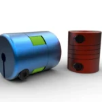
Jaw Couplings
The most typical form of jaw coupling is the one that is applied in general industrial hardware. It is made of two metallic hubs (typically aluminum, sintered steel or cast iron) with three or more protruding jaws. Between these jaws is placed a star-shaped elastomeric insert, called a spider. The torque is passed by compressing the legs of the spider between the jaws of one hub and the jaws of the other hub.
- Applications: Suited to centrifugal pumps, fans, blowers, and light-to-medium industrial mixers.
- Key Advantage: It is a fail-safe design. In case of wear-out of the spider, the metal jaws interlock and the power is still passed on, enabling a controlled shutdown instead of an instant systemic crash.
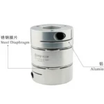
Disc/Diaphragm Couplings
Disc couplings make use of a stack of thin, stainless steel discs (usually in a pack) which are bolted to the driving and driven hubs alternately. These metallic discs are bent to provide flexibility.
- Applications: It is used in high-performance turbomachinery, gas turbines, and high-speed compressors where precision is not a compromise.
- Key Advantage: They provide very high torsional stiffness and backlash free. They are highly adapted to rapid rotation, and can survive severe chemical conditions that destroy elastomeric spiders.
Gear Couplings
The heavyweight of the mechanical flexing world is gear couplings. They are made of two hubs with external gear teeth and a sleeve (or two sleeves) with internal gear teeth. The teeth are normally crowned or rounded to permit angular misalignment.
- Applications: Steel mills, paper machines, and heavy-duty conveyors.
- Key Advantage: Power density. A gear coupling has the ability to transmit a greater torque than any other type of coupling of similar size. They are hard and with adequate lubrication, their service life is very high.
Grid Couplings
A grid coupling has two slotted hubs and is joined by a serpentine shaped spring grid of high strength alloy steel. The grid is allowed to slide in the slots of the hubs to allow misalignment.
- Applications: Find wide use in rock crushers, vibratory screens, and severe shock loading applications.
- Key Advantage: The grid has the capacity to bend and slide hence a great shock absorber. At high loads, the grid makes contact with the hub slots more completely, making the system stiffer and safeguarding it.
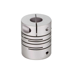
Bellows Couplings
Bellows couplings are made of a thin-walled, flexible metallic tube (the bellows) welded or bonded to two hubs. This design is highly flexible in every direction and torsionally rigid.
- Applications: CNC machines, high precision robotics and servo motors.
- Key Advantage: 100% zero-backlash operation and high precision. They are the benchmark of motion control in which the output should be an exact reflection of the input.
Tyre Couplings
These tire couplings are very flexible and are recognizable by their rubber or polyurethane element which looks like a miniature vehicle tyre. The tyre is clamped to two hubs and manages the misalignment by shearing the elastomeric material.
- Applications: Internal combustion engine drives, heavy-duty compressors, and applications with high parallel misalignment.
- Key Advantage: They are able to manage huge parallel offsets (up to 6mm or more) and offer the best vibration isolation of any type of coupling.
Chain Couplings
The chain coupling is a simple but strong design that is made up of two sprockets that are linked together by a roller chain of double strands. The clearance between the chain links and the sprocket teeth gives the flexibility.
- Applications: Low-speed, high-torque industrial motors and basic power take-off (PTO) systems.
- Key Advantage: Ease and simplicity of replacement. The chain is removable and unlinked without any motion of the motor or the driven machine.
Oldham Couplings
The Oldham coupling is a three-part design consisting of two hubs and a center floating disc (typically of plastic or bronze) that moves in grooves on the hubs.
- Applications: Stepper motors, actuators, and high precision positioning systems.
- Key Advantage: It is specifically made to accommodate high levels of parallel misalignment without generating high radial loads on the bearings.
How to Select the Right Type and Common Pitfalls to Avoid
The choice of the type of flexible coupling must be systematic and evidence-based. The aim is to identify a component that satisfies the torque needs without adding unjustified weight or complexity.
The Selection Checklist
- Calculate Torque Requirement: Use the standard formula to find the nominal torque (T):

Where P is power in kilowatts and n is speed in RPM.
For Imperial units:

- Apply Service Factors: Industrial loads are seldom constant. Depending on the severity of application, a service factor should be applied. A centrifugal pump may have a 1.25 factor, and a reciprocating crusher may have a 3.0 factor.
- Analyze Misalignment: Measure the anticipated parallel, angular, and axial offsets. Make sure that the type of coupling selected is rated to these values.
- Environmental Factors: Take into account the operating temperature and contact with oils or chemicals. Elastomers such as Nitrile have a lower temperature limit than stainless steel disc packs.
- Torsional Rigidity: Decide whether your system must be high precision (zero backlash) or whether it must be dampened (elasticity).
Common Pitfalls
- Over-Sizing: Engineers tend to choose a coupling that is much larger than required to be on the safe side. This introduces unwanted rotational inertia to the system that may introduce delays in response to servo systems and additional load on the motor during start-up.
- Treating the Coupling as a Universal Joint: These devices are flexible, but they are not supposed to substitute for correct shaft alignment. A coupling that is used at its maximum allowed misalignment will have a very short life because of heat accumulation and fatigue.
- Disregarding Ease of Maintenance: In high-uptime systems, the choice of a coupling that involves the complete movement of the motor to replace a simple spider is an expensive error.

Why Kunlong is Your Trusted Partner for High-Performance Couplings
In the specialized domain of industrial hardware, the distinction between a component and a solution lies in the manufacturer’s commitment to technical rigor. For over 20 years, Kunlong has refined this balance, serving twelve diverse industries ranging from telecommunications and medical devices to environmental test chambers and cold-chain infrastructure. Our operational philosophy transcends simple supply; we provide a holistic “Selection + Solution” framework, incorporating 3D model integration and one-stop technical services that bridge the gap from conceptual design to physical implementation.
Our production is characterized by technical accuracy. Our manufacturing tolerances are as tight as 0.0005mm, which means that we are stable in high-load conditions where even a microscopic variation can affect the performance of the system. We have stainless steel, special alloys, and high-performance elastomers in our material library that are certified by SGS and RoHS and have been designed to withstand extreme thermal gradients between -70°C and 260°C, as well as provide high corrosion resistance and load-bearing capacity.
This technical capability is reinforced by a rigorous quality-controlled manufacturing environment. Supported by a 10-person dedicated QC team and 30 seasoned engineers with an average of 10 years of experience, every batch undergoes a 15-point inspection to meet ISO9001, CE, and RoHS standards, ensuring 100% quality assurance. With over 600 unique functional customizations already implemented, Kunlong does not merely manufacture hardware; we engineer the reliability required for the modern industrial age.
Maintenance and Troubleshooting: Extending Service Life
The initial element that tends to exhibit systemic distress is a flexible coupling. It is not only the coupling that needs proper maintenance, but it is also about the health of the whole drivetrain.
Routine Inspection Protocols
- Visual Check of Degradation: In the case of elastomeric types (Jaw, Tyre), observe chalking (fine powder), cracks, or hardening of the flexible element. These are indications of ozone attack, heat aging, or chemical incompatibility.
- Lubrication Management: In mechanical flexing types (Gear, Grid), the lubricant should be clean and at the appropriate level. Grease leakage usually means that the seal is not functioning properly and will cause the teeth to wear out quickly.
- Hardware Tightness: Inspect the setscrews or clamping bolts. A slipped coupling on the shaft may result in serious damage to the keyway and the shaft surface.
Troubleshooting Failure Signs
- Abnormal Noise: A clicking sound that is rhythmic usually means that a gear coupling is dry or that a jaw coupling is worn away entirely by the spider, especially when operating at high speeds.
- Excessive Heat: When the coupling hubs are too hot to handle, then the coupling is probably overstraining itself to correct extreme misalignment, resulting in internal friction and energy loss.
- Vibration Spikes: When a formerly smooth system starts vibrating, it can be caused by the flexible element of the coupling losing its symmetry or the shaft position changing as a result of settling of the foundation.

Conclusion: Choosing Reliability for Your Drive System
One of the most significant choices in mechanical design is the choice of different types of flexible couplings. You may choose the ease of a Material Flexing design or the power of a Mechanical Flexing system, but the decision should be based on a clear understanding of your working conditions.
The soft connector is the silent guardian of your industrial property. It allows misalignment, shock absorption, and bearing protection so that your production lines are always running and your maintenance costs are always predictable. When you collaborate with a special manufacturer such as Kunlong, you can be confident that your couplings are manufactured to the utmost standards of accuracy and longevity. Reliability in the context of industrial power transmission is not a coincidence but rather a product of knowledgeable choice and quality design.
-150x150.webp)