


Introduction
The jaw coupling is one of the most widespread and at the same time most important elements in the huge ecosystem of industrial applications. As a preferred choice for engineers, it serves as the silent medium, the linkage between the propelling force of an electrical motor and the propelled load of a pump, compressor, or gearbox. While jaw type couplings might seem to be a straightforward solution—a combination of two metal hubs and an elastomeric spider—their contribution to vibration dampening, misalignment tolerance, and the ability to shield costly equipment against disastrous failure is immense.
Knowing the jaw coupling is not just knowing the parts; it is knowing the physics of the transmission of torque and the material science of elastomers. This guide is an ultimate source of information for engineers and procurement professionals, explaining the selection procedure, the peculiarities of spider materials, and the paramount role of accuracy machining in providing reliable service over a long time.
What is a Jaw Coupling?
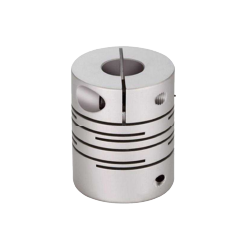
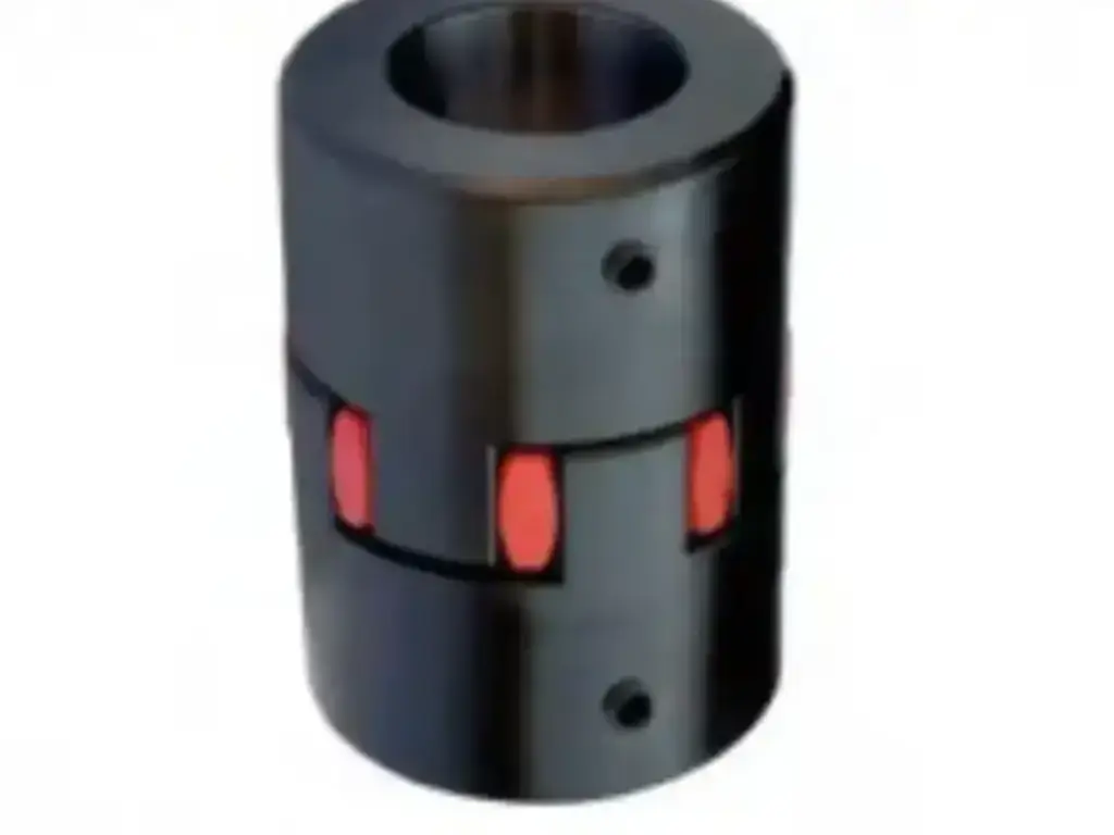
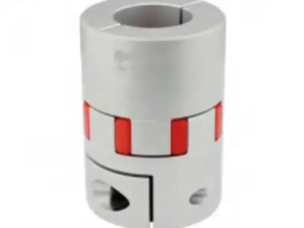
A jaw coupling is essentially a material-flexing coupling intended to transfer torque. Its basic transmission mode is compression-based, unlike rigid couplings or other forms meant for similar uses. The structural components feature a simple three-piece design: two metallic hubs and a central elastomeric insert. These hubs are available in different materials such as sintered iron, stainless steel, aluminium, and ductile iron, allowing for a wide range of applications.
The mechanism works by an interlocking system where the jaws of the two hubs interlock without making direct contact. The elastomeric spider fills the space between them, ensuring shaft separation and electrical isolation. As the motor rotates, the legs of the spider are squeezed to pass the rotation. This design can be operated under compression to enable the coupling to support much higher torque loads relative to its size compared to other flexible shaft couplings.
The mechanism works by an interlocking system in which the jaws of the two hubs interlock without making direct contact with each other because the spider fills the space between them. As the motor rotates, the legs of the spider are squeezed together by the jaws of the driving hub and the jaws of the driven hub to pass the rotation. This design can be operated under compression to enable the coupling to support much higher torque loads in comparison to its size than other flexible couplings.
One of the distinguishing features of the jaw coupling is its fail-safe nature:
- The jaw coupling has continuity of drive unlike shear-type couplings which break the connection when failure occurs.
- When the spider wears off or breaks, the metallic jaws of the two hubs will ultimately lock together (metal-on-metal) and keep on pushing the load.
- Although this state generates noise and wear, it does not cause a complete loss of transmission, which is essential to safety-heavy loads such as elevators or fire pumps.
Its main strengths are:
- The elastomer shock absorber and torsional vibration are absorbed, and the power delivery is smoothed out.
- It can tolerate unavoidable angular and parallel misalignment, sparing bearings and seals of undue radial loads.
- It does not need any lubrication, unlike gear or grid couplings, and is a cost-effective option in general-purpose power transmission.
The Heart of the System: Decoding the Spider (Insert)
Material Science & Selection: Hardness, Durability and Torque
The material properties of the spider, which is the fuse in the mechanical circuit, are the key determinants of the performance of a jaw coupling. Engineers have to balance between damping and torque transmission. Although spiders are usually color-coded, the use of visual pigment is a risky simplification, since a Red spider in Europe might mean something different than a Red spider in the American market. Thus, the Shore Hardness rating should always be the main point of reference of the engineer, differentiating the following main material categories:
- Nitrile Butadiene Rubber (NBR): The standard in the industry. NBR is usually characterized by black color and a hardness of 80 Shore A, which makes it the most effective in terms of excellent vibration dampening because it is relatively soft. It has a high resistance to oils and is therefore the default option in general industrial use with temperatures between -40C and +100C.
- Urethane: The high-performance upgrade. Urethane has a hardness of about 90-95 Shore A to 98 Shore A, polyurethane offers about 1.5 times the torque capacity of NBR. Although it loses a little damping capacity to its greater stiffness, it is superior in chemical-heavy applications where normal rubber would fail.
- Hytrel ® (Thermoplastic Polyester Elastomer): The heavyweight expert. Hytrel is a plastic-like material that is usually Tan or White and has a hardness of 55 Shore D. It provides superior stiffness and high-heat resistance to 120 o C. Nevertheless, this stiffness implies that it conveys much more vibration than NBR or Urethane.
- Bronze: The extreme environment solution. Solid Bronze spiders are used in applications where high heat or low speed is required and no elastomer can withstand it. These are highly restricted to low-RPM applications (usually less than 250 RPM) but are practically resistant to temperature and chemicals.
In order to overcome the possible confusion due to regional manufacturing standards, the following table gives a conclusive cross-reference of material hardness, major characteristics and their common color codes in various markets.
| Material | Shore Hardness | Typical US Color | Typical Euro Color | Key Characteristic |
| NBR (Rubber) | 80 Shore A | Black | Black | Max Damping, Standard Oil Resistance |
| Urethane | 90-95 Shore A | Blue / Orange | Yellow | Balanced Torque & Damping |
| High-Torque Urethane | 98 Shore A | Red | Red / Green | High Stiffness, Lower Damping |
| Hytrel® | 55 Shore D | White / Tan | White | Extreme Torque, High Heat (Plastic-like) |
| Bronze | Rigid Metal | Bronze | Bronze | Low Speed, Extreme Heat/Chemicals |
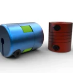
Design Differences: Solid Center and Open Center
In addition to material composition, the physical geometry of the spider is also important in application suitability. The most common design is the solid center spider, in which the legs are joined together with a solid web of material in the center. This hard core is essential in ensuring the structural integrity of the spider, especially when subjected to centrifugal forces that have the tendency of bending the legs outwards when rotating at a high speed. Open center spiders, on the contrary, do not have this middle web, leaving a hole in the center of the insert. This type of design variation enables the shafts of the driver and driven equipment to be brought much closer together, in effect permitting the shaft ends to almost touch within the coupling. This is especially beneficial in small machines where the Distance Between Shaft Ends (DBSE) is small, but it loses some of the high-speed stability of the solid center version.
Jaw Coupling types: Standard Industrial and Precision Zero-Backlash
The Standard “L-type” (Straight Jaw)
L-type or straight jaw coupling is the overwhelming majority of the couplings used in general industrial facilities. Here the jaws are cut with straight edges, and the spider is made to fit rather loosely between them. This loose fit is not accidental; it can be installed and removed with an incredible ease, also known as blind assembly, and it offers a large amount of room to accommodate shaft misalignment. But the distance between the spider and the jaws causes backlash, a momentary stagnation or free play as the motor changes direction. In continuous motion applications such as driving a water pump, a conveyor belt or a fan, this backlash does not matter. The L-type is more cost-effective, easy to maintain, and able to misalign than the positional accuracy.
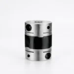
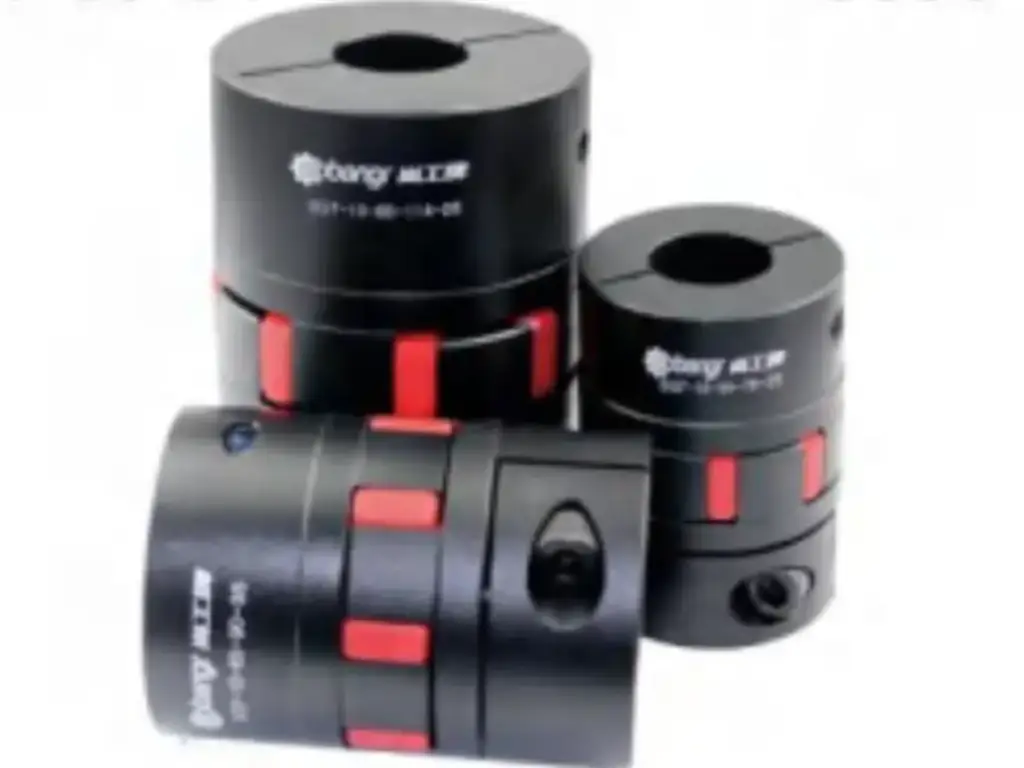
The Curved Jaw (Zero-Backlash)
The standard L-type cannot be used in the field of automation and motion control because it has a backlash. This requirement led to the Curved Jaw coupling, which is specifically intended to be used with servo motors, steppers, and positioning tables where precision is of the utmost importance. The hubs, unlike the straight jaw design, have a curved profile that is similar to a specialized spider. This spider is press-fitted into the jaws with high preload, and all gaps are removed, and there is no play whatsoever between the parts. The outcome is a torsionally stiff coupling that can withstand high torque densities. Moreover, these couplings are frequently matched at much higher rotational rates, even over 40,000 RPM. Such manufacturers as KUNLONG use the latest CNC technology to manufacture these hubs with high concentricity, which is required to satisfy the strict requirements of semiconductor and automation industries.
The Spacer Type
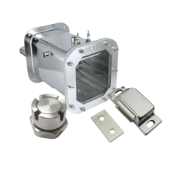
The Spacer Type jaw coupling was created to solve a particular and expensive maintenance issue that was observed in the fluid handling sector. In a typical installation, it may be necessary to unbolt and physically relocate the heavy motor or the pump casing to allow clearance to replace a pump seal or a worn coupling spider. The Spacer Type has a drop-out center section made of the spider and a metallic spacer element. This center section can be removed by just a few bolts, leaving a big gap between the hubs of the shafts. This space gives enough space to the maintenance personnel to reach and change pump seals without ever interfering with the alignment or location of the driver and driven equipment. This design will save a lot of time and labor during the maintenance of chemical plants and water treatment facilities.
Jaw Coupling Selection Guide: How to Size Right
Specifications of Jaw Coupling Products to be noted
It is essential to first collect the exact physical constraints of the system before starting the selection calculations. This is not just a question of torque but a three dimensional puzzle of geometry. You have to record the actual shaft diameters of the driving and driven equipment as these are usually different. Also record the keyway dimensions (standard square, metric, or shallow), and the largest physical envelope that can be used, namely the Maximum Outer Diameter (OD) and the Overall Length (OAL). Failure to observe these physical limits can result in the choice of a coupling that is torque-sufficient but physically inaccessible to fit into the machine housing.
Step 1: Identify Basic Operating Requirements and Operating Parameters
The initial analytical process is to consolidate the raw operations data of the application. You need to know the power output of the prime mover, whether in Horsepower (HP) or Kilowatts (kW) and the operating speed in Revolutions Per Minute (RPM). It is also important to define the nature of the application itself. What exactly is being driven? A centrifugal pump that runs smoothly acts in a very different manner compared to a rock crusher or a reciprocating compressor. The basis of this qualitative evaluation of the type of load is the basis of the safety margins that are needed in the next steps.
Step 2: Determine the Service Factor (SF)
Nominal torque of a motor refers to the output of the motor under ideal and steady conditions. The real world however, deals with shock loads, vibrations and rough starts. To consider this, engineers apply a multiplier, Service Factor (SF), to the theoretical load to make it a realistic design load. A Service Factor of 1.0 is standard with a system that has a uniform load, like a fan or centrifugal pump powered by an electric motor. When the application is light shock loads, e.g. belt conveyors or generators, the SF is 1.5. In the case of heavy industrial machinery with high torque spikes, such as reciprocating compressors or crushers, an SF of 2.0 to 2.5 is required. Also, when the prime mover is an internal combustion engine, and not an electric motor, then the SF must be further increased by 0.5 to 1.0 to represent the pulsating torque of the engine cylinders.
Step 3: Determine the Design Torque Required
After determining the Service Factor, the Design Torque can be determined. This number is the highest rotational force that the coupling should be capable of sustaining. The formula is associated with power, speed, and the service factor. In inch-pound units, it is calculated as follows: Design Torque (in-lbs) = (Horsepower x 63,025/RPM) x Service Factor. This mathematical conversion is essential since a high-horsepower motor at a very low speed produces enormous torque, which can be very large even when compared to the horsepower number alone.
Step 4: Choose Hub Size depending on Torque and Shaft Diameter
Having the Design Torque figure, go to the manufacturer catalog and locate a coupling size with a Nominal Torque Rating greater than your calculated Design Torque. But this is where most of the selection errors are made. You have to cross-reference the bore capacity of the coupling at the same time. It is quite common that the shaft diameter required may exceed the largest bore that can be used to fit the coupling size that meets the torque requirement. When this happens, the shaft diameter is the determining factor and you will have to increase the coupling size to fit the shaft, even though the torque rating will be larger than required.
Step 5: Select the Elastomer Material and Durometer
Based on the material science mentioned above, choose the type of spider. When the application environment has temperatures over 200 F or when it is exposed to aggressive oils and chemicals, you should switch off the standard NBR to Hytrel or Urethane. In case the environment is standard and the torque requirement is near the limit of the coupling capacity, it is often possible to replace the spider material with NBR with Urethane and still achieve the same torque requirements with a smaller, cheaper coupling size.
Step 6: Check Misalignment Capabilities and Installation Requirements
The last check is to make sure that the coupling you have chosen can accommodate the misalignment that is likely to occur in your system. Compare the angular and parallel misalignment ratings of the catalog with the real tolerances of your machine assembly. In case your system needs a lot of misalignment, a jaw coupling may not be the technology you need at all, and a universal joint may be needed. Also, ensure that the shafts have sufficient axial space to fit the hubs correctly and that the set screws are accessible.
Quick Selection Checklist
| Step | Action Item | Critical Consideration |
| 1 | Measure Shafts | Check both driver and driven shaft diameters and keyways. |
| 2 | Identify Load | Is the load smooth (pump) or jerky (crusher)? |
| 3 | Check Environment | Temperature, oil, chemicals, or wash-down requirements. |
| 4 | Calculate Torque | Apply the Service Factor before selecting the size. |
| 5 | Check Bore Capacity | Does the coupling size fit the largest shaft? |
| 6 | Review O.D. | Will the coupling physically fit in the housing? |
Jaw Coupling Uses: Strategic Implementation and Constraints
Jaw couplings are the infantry of the mechanical world. Nevertheless, to be successfully deployed, they need to align their particular strengths with the appropriate environment and avoid their weaknesses to the letter.
Core Applications: Where and How to Select
- Industrial Pumping (Centrifugal, Hydraulic, Gear Pumps): These couplings are common to join electric motors to fluid pumps. As pumps tend to produce fluid pulsations and hydraulic shock, the elastomeric spider of the coupling absorbs the vibrations, which do not pass on to the motor bearings and mechanical seals. In the case of standard water pumps, Cast Iron hubs are adequate. But in the case of chemical processing or washdown conditions, you need to indicate Stainless Steel (304/316) hubs to avoid corrosion. The better option in this application is the use of standard NBR (Nitrile) spiders due to their softness that offers the highest vibration damping needed to ensure the pump seals are not damaged.
- Compression Sector (Air and Refrigeration): This is necessary to operate heavy-duty reciprocating or screw compressors. Since compressors can have extremely high start-up torque, the robust design of the coupling must be able to absorb these spikes and reduce the torsional vibration of compression cycles. Ordinary rubber is usually too soft here. Hytrel (Urethane) spiders should be used in preference to ordinary NBR. Hytrel has much greater stiffness and torque capacity (usually 2-3 times standard) which is essential to deal with the aggressive start-up torque of large compressors without shearing the insert.
- Material Handling (Conveyors, Bucket Elevators): This is the standard transmission connection of the belt and chain systems. These systems experience abrupt changes in load (e.g. dropping heavy material onto a moving belt), and therefore the coupling is a buffer to smooth out shock loads that would otherwise break chains or strip gears. You should use Standard NBR spiders here, unlike the compression sector. High-torque (rigid) inserts should not be used in conveyors; the softer, more elastic material of NBR is required to physically absorb the shock impacts. An overly rigid spider will pass the shock on to the gearbox, which is the opposite of the point of the coupling.
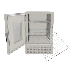
- Environmental Test Chambers: These are essential in fan and compressor operations within thermal chambers. The manufacturers such as KUNLONG are doing well in this specialized industry by offering hardware that is compatible with specialized high-temperature spiders so that the system can withstand extreme thermal cycling (-70 C to 260 C) without the metal seizing or the insert failing. Ordinary elastomers will not last long in this environment. You need to indicate Silicone spiders (extreme cold) or Bronze inserts (extreme heat). Also, the metal hubs are to be machined with a little bigger clearances to allow them to expand and contract without binding.
- Marine Propulsion (Small Vessels): This is used in small vessels to attach engines to propeller shafts. As marine engines generate a lot of torsional vibration, the coupling isolates this energy to the gearbox and propeller shaft, which minimizes noise and eliminates transmission wear. Here, there is no compromise on material choice. Hubs made of Stainless Steel must be able to resist saltwater corrosion; Sintered Iron will rust and seize. Moreover, the hardness of the spider (Shore A) must be adjusted to the frequency of vibration of the engine to prevent resonance problems.
Limitations: Where to Avoid (and the Risks)
Although jaw couplings are versatile, they are not a universal solution. Their application in the situations below may result in disastrous failure:
- Extreme Misalignment (Angular Offset > 1): The standard jaw couplings do not have the flexibility of cardan shafts or U-joints. Working outside the tolerance limit causes the spider to enter a loop of extreme compression, producing too much internal heat (hysteresis) to melt or shred the insert. In extreme situations, the resulting reaction loads may even bend the shafts.
- Precision Motion Control (Servo Applications): Standard L-type jaw couplings have a natural play between the jaws and the spider. This gap in servo systems causes backlash, which causes positioning errors, loss of accuracy, and instability in the control loop. (Note: Special “Curved Jaw” zero-backlash variants only can be used here).
- Extreme High Heat (>120C with Standard Inserts): Standard elastomers (NBR/ Urethane ) lose their structural integrity at high temperatures. Beyond this temperature, the spider will either be brittle or melted, resulting in direct metal-on-metal contact. This leads to sparking, high noise and ultimate destruction of the metal hubs. The better here is disc or bellows couplings.
- Zero-Maintenance: Elastomeric spiders are wear parts that need regular inspection and replacement, and thus do not fit well in places that need significant disassembly to reach (e.g. inside a nuclear plant or deep-sea equipment). The unplanned downtime caused by a worn spider in these locations is very expensive and therefore magnetic or non-contact couplings are a better investment.
Installation Procedures of Jaw Coupling
The life of a jaw coupling is almost completely decided during the installation stage. This is done by first cleaning the shafts carefully to eliminate any burrs, paint or debris that may interfere with concentricity. The hubs are then slipped on the shafts with the keys in place. The most important step is alignment; with a straightedge and feeler gauges (or a laser alignment tool in critical high-speed equipment) the technician should check that the angular and parallel misalignment is within the tolerances specified by the manufacturer. When in alignment, the gap is the point of focus. The installer should make sure that there is a certain distance between the metal faces of the two hubs when inserting the spider. The hubs should not be in contact with each other; this is to provide the spider with some room to stretch when compressed and to provide electrical isolation between the driver and driven equipment. After the spacing is right, the setscrews are tightened to specification.
Preemptive Maintenance Procedure
To maintain it efficiently, it is necessary to change the mindset of fixing it when it breaks to a proactive timetable. There are three non-negotiable checkpoints that should be inspected on a regular basis.
- Gap Verification: Check the feeler gauge to ensure that the “Distance Between Shaft Ends” (DBSE) has not been closed by thermal expansion; the hubs should not be in contact.
- Alignment & Fastener Integrity: Periodically recheck shaft alignment as foundations settle, and use a torque wrench on all set screws to avoid shaft fretting.
- The Spider Replacement Rule: Do not wait to fail. Immediately replace the elastomeric insert when you notice 25% decrease in the leg thickness or any surface cracking. When the spider wear is abnormally high even with good alignment, then upgrade to a precision machined hub to remove abrasive wear.
Decoding Jaw Coupling Failures: Symptom to root cause
In order to successfully sustain a jaw coupling, a person should be trained to read the physical indicators of failure. The following diagnostic guide is a map of visible symptoms directly related to their root causes and preventive measures.
- Audible Screeching and Sparks: When you can see the sparks or hear a screeching sound when using the system, the system is experiencing Axial Displacement. This particular failure mode is due to the fact that the necessary gap between the hubs was not taken into consideration during installation, and the opposing jaws were in direct contact with each other. When installing, always check the dimension of the E (axial gap) with calipers or a spacer bar to make sure that the metal hubs do not touch.
- Melting or Internal Liquefaction: The spider appears melted, deformed or liquefied inside out, the cause is Misalignment. Angular or parallel misalignment exceeding the tolerance of the spider (usually 1 o ) causes the material to enter into a vicious cycle of compression and relaxation. This creates internal friction (hysteresis) which essentially cooks the polymer structure. Check angular and parallel offsets with laser alignment tools or dial indicators to make sure that they are within the tolerance range given by the manufacturer (less than 1).
- Clean Shearing of Legs: Spider legs that look clean and sharp as though cut with a knife, are a sign of Torsional Shock. This pattern of damage proves that the system had experienced a sudden shock load or a huge torque spike that had surpassed the design limits of the coupling and sliced the elastomer before it could creep. Re-calculate the Service Factor of the system and increase the size of the coupling or high-torque Hytrel spider to accommodate peak loads.
- Fretting or Pitting on Hub Bore: Pitting, fretting or wear marks on the inside of the metal hub bore indicate Vibration problems due to mechanical fit. This is normally caused by loose shaft fit or set screws that have backed out because of system vibration and the hub is able to micro-move against the shaft. Use thread-locking compound to fix set screws and make sure that shaft tolerances are the same as the hub bore so that the fit is tight and secure.
- Swelling or Gelatinous Texture: When the spider has lost its shape and looks swollen, soft, or sticky to touch, it is undergoing a Chemical Attack. This texture modification proves that the elastomer material is not compatible with the oils, solvents, or chemicals in the operating environment. Determine the contaminant and replace with a Urethane or Hytrel spider with better chemical resistance.
- Brittleness & Cracking: A spider that has become hard, cracked or broken into pieces is a sign of Thermal Degradation. This brittle condition indicates that the surrounding temperature has surpassed the glass transition temperature of the material, baking the moisture out of the elastomer and depriving it of its plastics. To use higher operating temperatures (over 90C) use heat-resistant Bronze or Hytrel inserts instead of standard NBR rubber.
- Premature Abrasion: When the spider is abraded to powder or shreds much faster than anticipated, even with normal loads and alignment, the root cause is usually a Manufacturing Deficiency. In particular, bad metal hubs with coarse casting finishes are like sandpaper, scraping and grinding the spider off with each turn. Use smooth surface finishes on source precision-machined hubs to minimize friction and increase spider life.
The root causes of premature coupling failures are basically three visible categories, namely, Installation Errors, Operational Overload, or Environmental Incompatibility. But when a coupling fails even when perfectly aligned and in a controlled environment, the fourth and frequently ignored cause is the Manufacturing Deficiencies of the metal hub itself. This invisible variable is expressed in the form of rough casting surfaces which serve as sandpaper to rub the soft spider with each rotation, and in poor concentricity which produces destructive vibration and uneven distribution of loads, effectively destroying the system no matter how precise the operation is. Thus, to avoid such failures that are caused by hardware, there is a need to change the conventional casting techniques to precision engineering. This requirement of closer tolerances and finer finishes leads to the manufacturing requirements at KUNLONG, so that the metal hardware supports, and does not degrade, the elastomeric insert.
Effects of Precision Machining on Lifespan
The distinction between a coupling that fails too soon and one that provides a guaranteed 20,000+ cycle life is in the unseen aspects of production. In high-stakes industrial applications, the quality of the metal hub cannot be compromised. Although loose tolerances of about 0.05mm are usually tolerated in standard industrial hubs, high precision versions, like those produced by KUNLONG, have a tight tolerance control of 0.0005mm. This high precision is motivated by a group of 30 senior engineers and this guarantees the perfect concentricity so that the torque loads can be evenly distributed on all legs of the spider. This is an effective way of doubling the life of the elastomeric insert since it eliminates the uneven stress that causes rapid shear failure.
In addition to geometry, surface integrity is the most important. KUNLONG uses a 5-stage polishing to provide a mirror finish to the jaw interface, removing the microscopic abrasions that normally wear away elastomeric inserts. This attention to detail is confirmed by 1000+ hours salt spray test and ISO9001 and RoHS compliance. Having 15 different quality checks on each batch before it is shipped, the outcome is a hub that is not only a connector, but a precision tool that is meant to ensure the longevity of your entire drive system.
Conclusion
The jaw coupling is a misleadingly simple mechanism which does a complicated and necessary job. It is a guardian, a moderator, and a conduit of energy. Through the knowledge of the interaction between the torque needs and the spider materials, and the focus on the precision manufacturing, engineers can make sure that this small part will give years of trouble-free service. It is the first step towards operational reliability whether it is a giant industrial pump or a sensitive medical device; the proper choice of a jaw coupling is the key to success.
FAQS
Q: What is the distinction between jaw and spider couplings?
A: Jaw couplings are made with a metal hub and flexible spider to absorb shock, whereas spider couplings are made with an elastomer insert to damp vibrations and operate more quietly.
Q: What is the trouble shooting of a jaw coupling?
A: Inspect worn spider or hubs, misalignment and excessive vibration. Change damaged components and make sure that they are well aligned and lubricated.
Q: How to align jaw coupling?
A: Align shafts with alignment tools. Tighten the coupling by first adjusting to remove misalignment.