


Introduction
In the context of contemporary manufacturing, the difference between a prototype and a commercially viable product is frequently not the machine, but the tooling that enables it. Although Computer Numerical Control (CNC) machines and robotic arms are the muscle of production processes, jigs and fixtures are the skeletal structure, which gives the rigidity, correct orientation, and repeatability needed to be high quality at scale.
To the manufacturing engineer or operations manager, the design of these essential tools is an economic optimization exercise as much as it is a mechanical engineering exercise. An effective design of a fixture is not just one that holds a part, but it balances the variable costs of production volume. It converts the skilled labor needs into standardized machining operations and minimizes the statistical likelihood of mistake. This manual delves into the strict mechanics of jig and fixture design, starting with the basic concepts and then the economic reasoning behind their existence, and why the quality of each hardware part, such as the toggle clamps or positioning pins, determines the ultimate ROI of the manufacturing process line.
.webp)
What Are Jigs and Fixtures?
The words jig and fixtures are used interchangeably to the uninitiated. In the taxonomy of manufacturing, however, they have key differences in their functional roles, which are determined by their position relative to the cutting tool and the workpiece.
A Jig is a tool that serves two purposes at once: it secures the workpiece in place and, most importantly, it directs the cutting tool. The main aim of a jig is to create a relationship of accuracy between the tool and the specific parts without the operator having to measure or manually position the cutter. One of the most famous is a drill jig, in which a hardened tool guides the drill bit to the required coordinate. Jigs are typically employed in manual machining operations where the machine itself does not have precise positioning capabilities because the machining tool is controlled by the machine.
A Fixture, on the other hand, is single-purpose: it positions and holds the workpiece in relation to the machine axis. A fixture does not direct the tool as a jig does. Rather, it uses the machining tool (e.g. CNC mill) to manage the positioning path. The task of the fixture is to make sure that the workpiece is at the same coordinates (X, Y, Z) each time. The modern automated manufacturing process is based on fixtures, with the machine supplying the accuracy, and the fixture plates supplying the stability of the workpiece.
Components and Hardware needed to construct Jigs and Fixtures
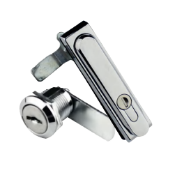
The effectiveness of any tooling arrangement depends on the integrity of the parts that make it. A chain is as strong as its weakest link, and so is a fixture, and its clamping and locating hardware.
.webp)
- Locators (pins, stops and pads): Determine the datum lines and physical reference points on which the workpiece is supported. They are essential in high-repeatability systems, where you can use the 3-2-1 rule, where each part, the first to the thousandth, is machined in the same location.
- Clamps: Are the active force agents, of which toggle clamps are especially common due to their rapidity and great holding force. They are essential in high-volume load-and-go processes (such as welding or assembly lines), where the time spent in slow manual wrenching can be replaced by immediate mechanical locking to save a lot of time.
- T-Slots: These are modular slots that are usually incorporated into the base plate or machine table to enable quick reconfiguring. They are best suited to high-mix, low-volume production, allowing operators to support different part sizes or design modifications without the expense and time of constructing an entirely new base of fixtures.
- Tooling Balls: These are precision-ground balls that are used as a fixed spatial reference point (X, Y, Z) to the machine. They are necessary in 5-axis machining and CMM inspection, where the machine can immediately dial in the precise position of the fixture with respect to the spindle or probe.
- Supports: e.g. jack screws or spring-loaded pins, ensure that the workpiece does not deform or vibrate under machining forces. They are applied particularly in machining thin-walled components to prevent chatter, or to give solid support to the irregular, uneven surfaces of castings and forgings.
- Bushings: These are hardened steel sleeves that are used to direct drills and reamers in operation. They are essential to manual drilling to provide straightness and are commonly employed to prevent the wear of softer materials of the fixtures, such as aluminum or 3D-printed plastics, during repeated cycles.
Why Invest in Tooling? The main advantages of Jigs and Fixtures
The choice to adopt specific tooling is an investment in process capability. Although the initial investment may be high, the payoff in operations is realized in five measures:
- Improved Productivity: Jigs and fixtures remove the manual marking, measuring, and tentative positioning of parts. The loading and unloading process is simplified and the machine uptime is maximized and the daily throughput increases linearly.
- Precision (Interchangeability & Repeatability): Tooling provides a fixed reference frame. This guarantees that the 10,000th part is geometrically equal to the first. This is the repeatability that is the basis of mass assembly, where parts can be interchangeable without being custom fitted.
- Cost Reduction: The need to have highly skilled operators reduces as the requirement of the tool is to have the skill embedded in it. A less experienced operator can machine a complex part provided the part is not loaded incorrectly by the use of a fixture. Moreover, the low scrap rates directly decrease the material costs.
- Reduced Setup Time (SMED): In high-mix low-volume production, the time lost in changing over between jobs is lost revenue. Quick-change fixtures and modular tooling can greatly decrease this downtime, enabling smaller economic batch sizes.
- Better Safety: A well-designed fixture holds the workpiece in place and usually blows the chips off the operator. The danger of industrial accidents is reduced significantly by eliminating the necessity of the operator to hold or manually stabilize parts close to moving cutters.
Types of Jigs and Fixtures
Classification of Jigs
Jigs are mainly created to direct the cutting tool (such as a drill or reamer) and to clamp the workpiece in place. They are usually classified according to their structure and mode of loading.
| Type | Core Feature | Primary Function |
| Template Jig | Simple plate placed directly on the workpiece. | Marking or drilling simple holes; low cost for large plates. |
| Plate Jig | Rigid template with clamping mechanisms. | Accurate drilling of hole patterns; better stability for medium parts. |
| Channel Jig | U-shaped structure, locating on three sides. | Support and locate elongated or thin parts; simple and rigid. |
| Box Jig (Closed Jig) | Fully encloses the part; multi-face access. | Complex operations on multiple faces in one setup; high precision. |
| Leaf Jig (Hinged Jig) | Features a hinged plate/leaf for quick access. | Fast loading and unloading; high production efficiency. |
| Indexing Jig | Includes an indexing mechanism. | Operations requiring precise angular spacing in a single setup. |
Classification of Fixtures
The main purpose of fixtures is to hold, support and position the workpiece on a machine tool or during assembly, but not to guide the cutting tool (the tool path is controlled by the machine itself). They are typically classified according to the machine or operation they are supporting.
| Type | Core Feature | Primary Function |
| Milling Fixture | Holds parts securely, resisting high cutting forces. | Machining on milling machines; ensuring stability under heavy load. |
| Turning Fixture | Mounts directly onto the lathe spindle. | Holding asymmetrical or irregular shapes for turning operations. |
| Grinding Fixture | High-precision, stable clamping. | Ensures parts remain stable and precise during delicate grinding. |
| Welding Fixture | Holds components in alignment, resists heat distortion. | Precise positioning and support during the welding process. |
| Assembly Fixture | Fixes component positions during joining. | Positioning support for assembly, fastening, or bonding. |
| Inspection Fixture | High-accuracy positioning for measurement. | Quality control; ensuring measurement repeatability and accuracy. |
| Indexing Fixture | Allows precise angular rotation of the workpiece. | Enables multi-surface machining or inspection on one machine setup. |
6 Principles of Effective Jig and Fixture Design
The design of a jig or a fixture is concerned with repeatability, accuracy and efficiency at the lowest possible cost. In order to do this, any successful design should follow six basic engineering principles.
Use the 3-2-1 Principle to Secure Part Location
Kinematic location is based on the 3-2-1 principle. In order to place a workpiece correctly in 3D space, it is necessary to limit its 12 degrees of freedom (linear and rotational movements). The principle is quite straightforward yet uncompromising: three points to define the main plane (limiting movement along the Z-axis and rotation along the X/Y), two points to define a side edge (limiting movement along the Y-axis and rotation along the Z axis), and one point as a final stop. Failure to follow this order will result in either an unstable workpiece (under-constrained) or a workpiece that will rock (over-constrained) and produce inconsistent machining.
Clamp to avoid workpiece distortion
Clamping is also confused with locating, which are used in different purposes. Whereas locators fix position, clamps merely fix it relative to cutting forces. The Golden Rule is to never clamp on the opposite or above a fixed support point. Do not clamp across an unsupported gap. When you do, the workpiece becomes a beam and bends under pressure. After the release of the clamp, the material springs back, leaving a part that is out of tolerance. Toggle Clamps are better than screw clamps when it comes to high-volume production because they offer a consistent preset pressure independent of the strength of the operator.
Safety and Poka-Yoke (Mistake-Proofing) Integration
A good design of a fixture takes into consideration the Human Factor. When a part can be loaded wrong, sooner or later it will be. Here is where Poka-Yoke (mistake-proofing) comes in: make the design of the fixture such that the workpiece can only be inserted in the right orientation. Safety is of utmost importance besides quality control. The design should be such that it removes pinch points, covers sharp edges and that the metal chips (swarf) can be easily removed without the operator having to reach into hazardous areas.
Ergonomics: Operator Efficiency and Comfort Design
Cycle time is a direct result of ergonomics. When loading a part involves awkward wrist movements or excessive force, operator fatigue will be established, reducing the pace of production and error rates. Design to the Golden Zone of motion. Make sure that there is plenty of clearance around hands (even when wearing gloves), and make sure that the hardware used is quick-acting and can be operated with one hand. A 5-second reduction in the time per cycle on a 100,000-part run saves almost 140 hours of labor – pure profit saved by merely thinking about the comfort of the operator.
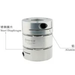
Material Choice: Strength, Weight, and Cost
The selection of the appropriate material is a balancing exercise that is strategic in terms of durability (wear resistance) and stability versus weight and cost. Not all parts require costly tool steel, and not all locating surfaces should be made of soft aluminum.
The selection of the correct material to use in a given fixture is a matter of strength, weight, and cost as illustrated in this comparative overview.
| Material | Best Application | Why Choose This? |
| Hardened Tool Steel | Locators, bushings, supports | Maximum Durability. Essential for contact points that endure repetitive friction. |
| Mild Steel | Structural bodies, bases | Cost-Effective Strength. Cheap and strong, but requires coating to prevent rust. |
| Aluminum (6061) | Large plates, moving parts | Lightweight Efficiency. Ideal for reducing operator fatigue and machine load, though it dents easily. |
| Cast Iron | Heavy milling bases | Vibration Dampening. Provides superior stability for heavy machining but is heavy and brittle. |
| Synthetic/Nylon | Clamping surfaces | Non-Marring. Perfect for holding delicate finished parts without scratching them. |
Suggestion: Adopt a mixed method. Add an aluminum base to reduce weight and hardened steel bushings to provide accuracy and KUNLONG stainless steel hardware to resist corrosion.
Justify Design Costs through Maximizing Tooling ROI
Engineers have to explain the complexity before a design is finalized. The complexity of the jig should be equal to the volume of production. Simple modular kits or standard vises are adequate when the volume of the run is low. In high-volume production, special purpose custom fixtures should be invested in to minimize the cycle time. The best solution to enhance ROI is to adopt standard industrial parts (such as handles and clamps) instead of creating unique parts. This reduces the initial build cost considerably and future maintenance is quicker and less expensive.
How-to Guide: The Jig and Fixture Design Process
The art of designing effective tooling is not an abstract art, but a methodical constraint management process. This is a structured workflow to make sure that a CAD model is accurate, safe, and long-lasting to transform it into a working production tool.
Step 1: Pre-Design Analysis and Requirements Definition
Design process does not start with drawing, but with a profound questioning of the workpiece print and the machining environment. First, define your Datum Strategy. When you have a rough casting, you need to establish three distinct target points on the raw surface to serve as your primary datum. In the case of pre-machined parts, the largest flat surface should be chosen to be stable.
Then specify your Tolerance Allocation. One of the most popular guidelines is the so-called 30-50% Rule, which states that the natural tolerance of your fixture should be much smaller than the part it is making, that is, it should not use up more than 30-50 percent of the allowable error of the finished part. Lastly, check the Machine Envelope. Test the Z-axis travel and table load capacity; a too-tall fixture can literally be unable to fit through the automatic tool changer (ATC), necessitating a complete redesign.
Step 2: Core Structure and Workpiece Orientation
After requirements are established, establish the position of the part in 3D space. The main objective here is Force Management. The workpiece should always be positioned in such a way that the major cutting forces act into the fixed, rigid body of the fixture, not against the clamps. Clamps are made to keep the part in place, not to struggle with the entire shear of a face mill.
In the case of the fixture body itself, the choice of material is important. In high volume production runs, Cast Iron or Stress-Relieved Steel should be specified due to its better vibration dampening and wear resistance. Nevertheless, when dealing with large fixtures that need to be loaded manually or changed regularly, 6061 Aluminum is usually a superior option to minimize the operator fatigue.
Step 3: Choosing Locating and Clamping Components
This is the point at which theoretical geometry collides with physical reality. To avoid binding, or a part becoming stuck because of minor differences in the spacing of holes, use the Diamond Pin Strategy. You can use a round pin to position your X/Y position and a diamond (relieved) pin to position your rotation.
In choosing clamps, leave guesswork behind. Estimate the cutting forces and multiply by a Safety Factor of 2x to 3x to get the holding force required. Select the hardware setup that fits the operation: Vertical Toggle Clamps are used in drilling operations where the arm needs to clear the loading zone entirely, and Edge Clamps are used in face milling operations where the entire top surface of the part needs to be clear.
Step 4: Design Optimization: Safety, Ergonomics, and Cost
It should not be a functional fixture, but a production-ready one. Chip buildup is the largest adversary of accuracy. Use the Relief Rule: never make flush surfaces where chips may be collected. Rather, apply raised locator pads (bosses) to form clearance under the part and design angled channels to allow the coolant to naturally cleanse chips off datum points.
Moreover, suppose that the operator will be distracted at some point. Include Poka-Yoke (Mistake-Proofing) characteristics, like a simple interference pin or block, so that it is physically impossible to load the workpiece backwards or upside down. Lastly, Serviceability design. Do not machine high-wear datum surfaces into the body of the fixture. Rather, wear pads or inserts made of hardened steel can be used. Once tolerances have drifted, a replacement of a $10 insert is much less expensive than scraping a $5,000 base of a fixture.
Step 5: Final Check and Handoff of Manufacturing
A virtual audit should be done on the design before metal is cut. Load the fixture model into your CAM environment to perform a Kinematic Simulation. Most importantly, ensure that the tool holder diameter is not interfered with, not only the cutting tool; short tools can easily lead to the spindle nose crashing into tall clamps.
Check the design ergonomics also. In case the weight of the fixture exceeds 15kg, the safety standards require that you incorporate threaded hoist rings or lifting slots to avoid injury. Lastly, mark certain QC Reference Points on the drawing- a tooling ball position or a particular bored hole. This will enable the Quality Control department to confirm the accuracy of the fixture to the machine origin prior to the commencement of the first production run.
The Economics of Tooling: ROI and Break-Even Break-even
In order to be rational, a company should determine the break-even point at which the savings of the tooling will be greater than the cost. The simple tooling economics equation can be stated as:
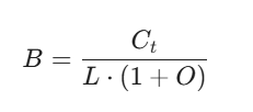
Where:
B= Break-even number of units.
C t = The total cost of the design, materials and construction of the fixture.
L = Labor savings/unit (Time saved x Labor rate).
O = Overhead rate on labor.
When the production order is above B, the tool is a profitable asset. Otherwise, less complicated clamping techniques are to be employed. Moreover, it is necessary to take into account the Cost of Quality. When a part of high value cannot be scraped at 2% by a fixture, the ROI is achieved much sooner than by labor savings alone.
Industry Applications: CNC Machining to Assembly
The usefulness of fixtures cuts across industries, but the needs vary greatly based on the industry.
- Automotive: Weld fixtures of high volume require high levels of durability and heat resistance. They frequently use pneumatic clamps that are heavy-duty and used to hold chassis parts when welding with robots.
- Aerospace: Large assembly fixtures can be laser tracked because of the sheer size of the components. Rigidity is the most important to avoid deflection of large aluminum wings or fuselage sections.
- Medical Equipment Production: Surgery is needed. The fixtures in this case are usually made of stainless steel or medical grade plastics to avoid contamination and must be capable of holding small, complex geometries (such as implants) without damaging the surface.
- Environmental Testing: Environmental chambers (a major industry that needs powerful hardware) manufacturers use fixtures to contain products in ovens or freezers. In this case, the fitting and the latching fittings should be able to survive the temperature variations between -70C to 260C without freezing.
- Electronics: Miniature fixtures to be soldered or assembled must be highly precise and electrostatic discharge (ESD) safe.
- General Heavy Machinery: In the case of agricultural or construction machinery, fixtures are huge, and parts may have to be loaded with cranes. It focuses on clamps with heavy loads and durability.
.webp)
The importance of Component Quality to Long-term Precision
A promise of accuracy is fixed, but it operates in a violently dynamic environment. It has to survive the harmonics of high-speed machining, corrosive coolants and the repetitive stress of thousands of cycles. Here, the mass of the steel base does not determine long-term accuracy, but the integrity of its moving parts.
The most severe risk to this accuracy is the so-called tolerance drift. Generic toggle clamps and latches can work in the setup, but they are not always as metallurgically rigorous as needed to be stable. With time, mechanical hysteresis is added by soft rivets and poor quality springs- small internal play that enables the workpiece to vibrate or move under load. In high-stress industries, inferior surface finishes result in quick corrosion and seizure, making a fine tool a liability.
The cost of inferior hardware is a hidden cost to your production, in the form of scrap parts and downtime in recalibration. In order to inoculate your process against this degradation, the hardware selection criteria should change to be based not on mere availability but on demonstrated endurance. It needs elements supported by strict lifecycle testing and material certification, which is exactly the quality of engineering that characterizes the product ecosystem at KUNLONG.
Take Your Tooling Design to the Next Level with KUNLONG Industrial Hardware
In order to ensure the ROI that you have determined during your design stage, the hardware that you choose should be a precision tool, rather than a generic consumable. KUNLONG solves this by implementing a 0.0005mm error tolerance on important parts, so that your fixture is as accurate as your CNC machine can be.
We know that downtime is profit killing. This is the reason why each batch is subjected to a stringent 15-point inspection to guarantee quality 100 percent. Our parts are designed to last 20,000+ working cycles and last 1,000 hours of salt spray testing, which provides high durability against the harsh coolants that tend to corrode conventional parts.
The team of 30 R&D engineers who steward this standard has an average of 10 years experience in industrial structural design. KUNLONG has complete SGS and RoHS material certifications, which provide not only hardware, but also the engineering confidence needed to produce high-precision products.
The Future of Jigs and Fixtures Technology
The future of tooling is dynamic. We are heading to smart fixtures, which have IoT sensors that measure the clamping pressure in real-time and inform the machine controller when a part is loose. Also, additive manufacturing (3D printing) is transforming the Build stage of the design process, enabling complex, conformal shapes of fixtures that could not be machined before. But despite the fact that the bodies of these fixtures are printed polymers, the requirement of strong, metallic interface hardware the locks, hinges, and clamps is always there.
Conclusion
Learning how to design jig and fixtures is not about developing complicated equipment; it is about developing certainty. It is the act of bringing order to the anarchic forces of production. Engineers can change their production lines by following the principles of location, using the right clamping forces, and determining the economic justification of each feature.
Finally, it is aimed at efficiency. And efficiency needs trustworthy associates. It is the quality of your tooling that determines the stability of your process whether you are machining a simple bracket or assembling a complex aerospace component. Invest in design, invest in good hardware and the payoff on investment will be a mathematical inevitability.