


Introduction
The choice of a shaft coupling is hardly a convenience; it is a basic choice in mechanical power transmission that determines the balance between the efficiency of power transmission and the life of the system. The coupling is the crucial backbone in the design of a drivetrain, linking the motive power to the functional load across various industrial applications. This decision is controlled by a strict evaluation of mechanical limitations, such as torque demands, rotational rates, and the unavoidable fact of shaft misalignment.
The right choice of a rigid or a type of flexible coupling not only influences the initial performance of the assembly, but also the fatigue life of bearings, seals, and shafts in the long term. This paper offers an analysis framework that can guide engineers to negotiate these trade-offs in order to achieve maximum system reliability.
What Is a Rigid Coupling
A rigid coupling, as the name implies, is a type of connection that is meant to provide a fixed, non-yielding relationship between two shafts. Mechanically, it considers the driver and the driven shafts as one continuous unit, making them suitable for a range of applications. Since such mechanical couplings lack any internal parts that can absorb movement, they must be perfectly aligned between the two connected shafts to be used without causing disastrous stress.
The main categories of rigid couplings are sleeve (or muff) couplings, clamp-style (split-muff) couplings, and flange couplings.
- Muff coupling (or sleeve coupling): the simplest which is a hollow cylinder with a keyway.
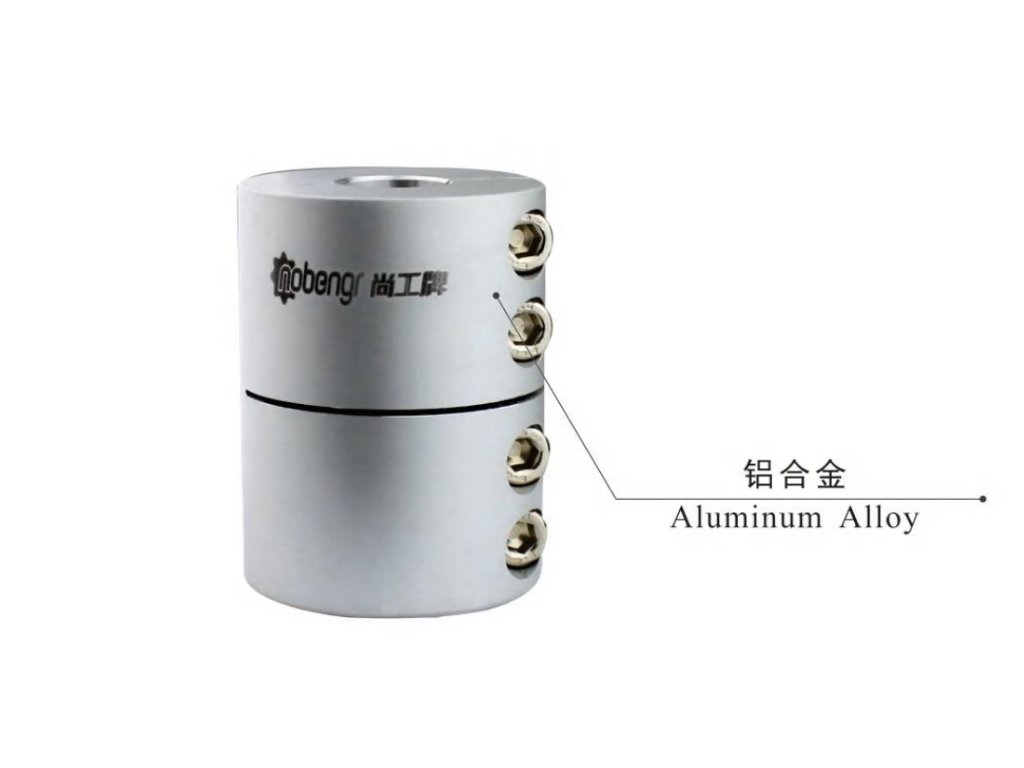
- Clamp-style (split-muff) couplings: It has the benefit of being simpler to install and adjust, because they are wrapped around the shafts and held in place with bolts to form a high-friction grip.
- Flange half coupling: These are heavier industrial couplings, which are made of two distinct flanged ends, which are connected by bolts, to give a strong connection to high-torque transmissions.
The hallmark of a rigid coupling is that it cannot correct any degree of misalignment. But this is the very thing that makes it possible to achieve maximum torque density and torsional stiffness. In systems where the timing or coordinated movement is of the utmost importance, the rigid coupling is the tool of choice since it removes the hysteresis or lag that could be experienced in the flexible options.
What Is a Flexible Coupling
Conversely, a type of flexible coupling is designed to be an elastomeric element mechanical buffer, which is meant to allow different levels of shaft misalignment and still be able to transmit torque. It acknowledges the empirical fact that it is not always possible to achieve perfect alignment because of thermal expansion, vibration or structural settling with time. A flexible coupling acts as a safety valve to mechanical stress and the system is able to work under imperfect conditions without failure.
Different types of flexible couplings are classified by the means by which they accomplish this motion: by mechanical friction, metallic flexion, or elastomeric resilience.
- Mechanical Flexible Couplings: These include the gear coupling, chain couplings, and roller chain couplings, which are based on the sliding of the mating parts to enable movement. They are usually applied in heavy-industrial settings with high torque.
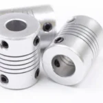
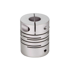
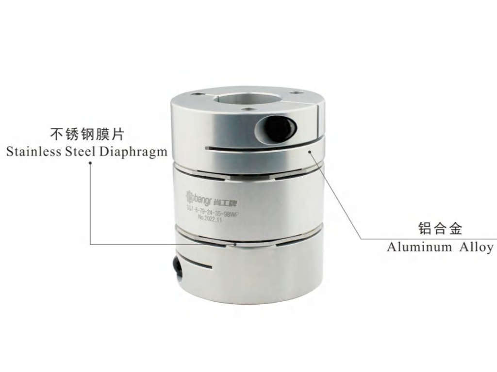
- Metallic Flexible Couplings: These are disc or bellows couplings, which take advantage of the thin, flexible nature of metal sheets or tubes to allow misalignment without any moving components, and are therefore suitable in high-speed, high-precision applications.
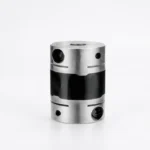
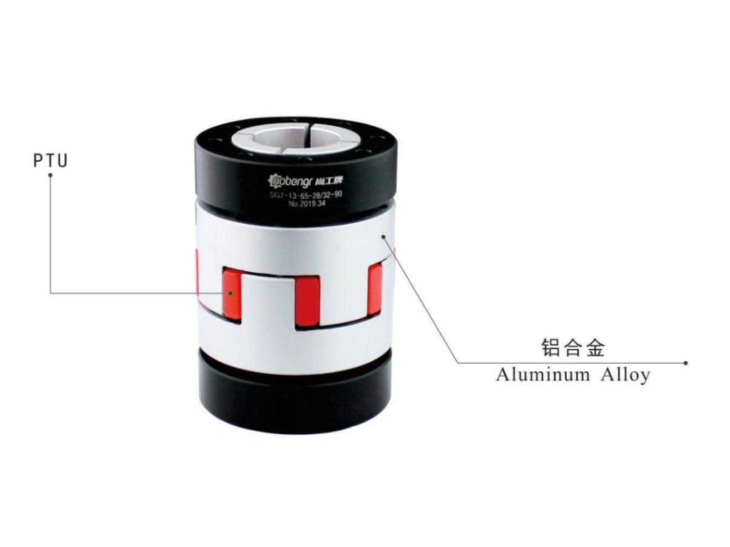
- Elastomeric Couplings: e.g., the Jaw Coupling (Spider coupling) or tire couplings or bush couplings, involve a rubber or plastic component to fill the gap. They are very useful in reducing vibration and shock loading sensitive equipment.
The flexibility of these designs cushions the more costly parts of the drive train, namely the motor bearings and gearbox seals, by absorbing the parasitic loads caused by misalignment.
Rigid Coupling vs Flexible Coupling: Key Performance Comparison
Misalignment Compensation Ability
The difference between these two types is most evident when considering the reaction to the axial, radial (parallel), and angular misalignment.
In a rigid coupling system, reactionary forces are produced by any deviation of a perfectly straight common axis. The stress will be applied directly to the shafts and the bearings since the coupling will not bend. A misalignment of a few thousandths of an inch can cause localized heating, vibration and premature bearing fatigue. Thus, rigid couplings can be used only in case the mounting surfaces are machined accurately and the alignment is checked using laser equipment.
Flexible couplings on the other hand are constructed with a certain misalignment capacity. A disc coupling may allow 1 degree of angular misalignment, whereas a jaw coupling may allow both angular and small parallel offsets by compressing its elastomeric spider. This load-bearing capability makes sure that the drive system does not stop working when the environmental conditions cause the machinery move slightly.
Torque Transmission Efficiency and Backlash
The strongholds of the rigid coupling are efficiency and precision, along with their high torque capacity. In the absence of flexible elements, there is zero “backlash”—the play or lost motion between the input and output shafts. This renders rigid couplings essential in CNC machines, medical robots, and high-speed printing presses where precision shaft alignment is crucial, as a fractional degree of error in shaft position can spoil the product.
Although efficient, flexible couplings tend to add some torsional softness. Elastomeric couplings, especially, can wind-up during high torque loads. Although certain high-performance flexible designs, such as the bellows coupling and diaphragm couplings, are promoted as being zero-backlash, they nevertheless cannot be compared to the absolute torsional rigidity of a solid steel clamp coupling. In the case of engineers, the trade-off is obvious: either the absolute accuracy of a rigid connection or the protective strength of a flexible one.
Vibration Dampening and Shock Absorption
Mechanical systems frequently experience shock loads, or sudden spikes in torque, or harmonic vibrations due to the motor or the process (a pump with slurry).
Rigid couplings do not stop vibration; they pass all the vibrations between the motor and the load and the other way round. This may cause resonance problems that may destroy delicate electronics or loosen fasteners all over the machine.
Flexible couplings, in particular those based on elastomers such as Jaw Couplings, are good at vibration damping. The elastomeric component (the “spider”) is a dampener, which transforms kinetic energy of vibration into a little thermal energy. This isolation is essential in such applications as air conditioning compressors or internal combustion engine drives, where the pulses of the power source would otherwise break the drivetrain components.
Strategic Application: When to Opt for Rigid vs. Flexible
The choice of the appropriate type of coupling is largely dependent on the environment in which the machinery is to be used and the objectives of the machinery.
When to Choose Rigid Couplings:
- Strict Alignment Possible: In cases where the equipment is mounted on a heavy, precision-machined baseplate made of carbon steel where alignment is possible.
- Synchronized Motion: In those applications where the driver and driven shafts need to be in precise phase (e.g., timing shafts).
- High Torque in Small Envelopes: Rigid couplings have the highest torque capacity in their size.
- Support Requirements: Sometimes a rigid connection is employed to enable one shaft to carry the weight of the other (in vertical pump applications).
When to Choose Flexible Couplings:
- Inherent Misalignment: When the machine is attached to a structure that is prone to vibration, thermal expansion, or movement in various industry applications.
- Bearing Protection: In cases where the cost of replacement of motor bearings is greater than the cost of a more expensive coupling.
- Shock Loading: In crushers, conveyors or mixers where the load may suddenly grab or spike.
- Ease of Maintenance: A wide variety of flexible couplings (such as split-jaw designs) can be maintained without relocating the motor or the driven equipment.
Rigid vs. Flexible Coupling: Quick Comparison Table
In order to generalize the technical information presented, the table below gives a comparative analysis of the performance parameters of the two types of couplings. This can be used as a main source of the first screening stage of the design process.
| Feature | Rigid Coupling | Flexible Coupling |
| Misalignment Capacity | Zero (Requires precision alignment) | Moderate to High (Angular, Parallel, Axial) |
| Torsional Rigidity | None (Transmits all vibration) – Quickly accessible for easy installation. | Variable (Low to Moderate) |
| Vibration Dampening | None (Transmits all vibration) | Excellent (Especially elastomeric types) |
| Bearing Load | High (Significant stress if misaligned) | Low (Coupling absorbs parasitic forces) |
| Complexity | Simple (Fewer moving parts) | Moderate (Multiple components/inserts) |
| Maintenance | Low (Periodic bolt torque checks) | Variable (Inspection of wear elements) |
| Relative Cost | $ to $$ | $$ to $$$$ |
| Primary Applications | CNC machinery, vertical pumps, precision servo systems, and short-shaft connections. | Conveyors, HVAC systems, compressors, and heavy industrial drives with shock loads. |
A Comprehensive Selection Checklist for Engineers
An engineer should measure the following variables before making a final decision on a coupling specification to make sure that the system is in equilibrium:
- Torque Requirements: What is the operating torque, and more to the point, what is the peak startup torque?
- Rotational Speed (RPM): Balanced couplings are needed in high-speed applications to avoid high-speed centrifugal vibration.
- Shaft Sizes and Tolerances: Are the shafts imperial or metric? How well does it fit (clearance vs. interference)?
- Expected Misalignment: Will the installation team be able to attain alignment within 0.001 inches or is 0.020 inches more realistic?
- Environmental Factors: Will the coupling be subjected to high temperatures (which may degrade elastomers), corrosive chemicals, or wash-down conditions?
- Serviceability: What is the allowable downtime? Can the wear parts be replaced in place by the coupling?
- System Dynamics: Does it have a danger of harmonic resonance that must be damped with certain coefficients?
Engineered for Reliability: How KUNLONG Professional Coupling Solutions Solve Your Challenges
In a marketplace defined by rigorous mechanical demands, KUNLONG has served as a benchmark for reliability since 2005. We recognize that an engineer’s primary objective is the maximization of uptime without compromising system protection. To meet this, we maintain a vast portfolio of over 3,000 standard products, while offering bespoke engineering for applications that defy off-the-shelf solutions.
Our technical authority is anchored by a team of 30 engineers, each bringing an average of 10 years of field expertise to the drafting table. This deep institutional knowledge enables us to achieve extraordinary precision, with tolerances strictly controlled within 0.0005mm. Every component is subject to a 100% quality control protocol, reflecting our commitment to the quality of management, and carries CQC, ISO, CE, and RoHS certifications.
Particularly with our Jaw Couplings, we provide a fail-safe mechanism that preserves your drivetrain’s integrity even under duress. We secure your investment with a comprehensive warranty of one year or 24,000 cycles on our qualified products. Choosing KUNLONG is more than a purchase; it is a strategic decision to minimize parasitic loads and ensure the long-term viability of your mechanical assets.
Installation and Maintenance Best Practices to Prevent Premature Failure
Even the most sophisticated coupling will fail if the installation violates the laws of physics. To ensure the longevity of the connection, several best practices must be observed.
First, alignment is not optional. Even when using a flexible coupling, the closer the alignment is to zero, the longer the life of the coupling and the connected bearings. One should never use the maximum rated misalignment of a coupling as the target for installation; rather, that capacity should be reserved for operational shifts.
Second, fastener torque must be verified. For clamp-style rigid couplings or bolted flanges, improper bolt tension can lead to fretting corrosion or total shaft slippage. Use a calibrated torque wrench and follow the manufacturer’s sequence.
Third, scheduled inspections are vital for flexible couplings. Elastomeric inserts should be checked for signs of “compression set,” cracking, or chemical degradation. In gear-type flexible couplings, lubrication levels and grease quality must be maintained to prevent metal-to-metal wear. A proactive maintenance stance—replacing a $50 spider during a scheduled stop—prevents the $5,000 failure of a motor during peak production.
Conclusion
The decision between a rigid and a flexible coupling, such as a spring coupling, is a study in mechanical trade-offs. The rigid coupling offers unparalleled precision and torque density but demands an environment of perfect alignment and stability. The flexible coupling offers a pragmatic solution to the realities of industrial operation, providing a resilient interface that protects the system from vibration and misalignment at the cost of some torsional stiffness.
By systematically evaluating torque, speed, and environmental constraints, and by partnering with a manufacturer like KUNLONG that prioritizes precision and material integrity, engineers can ensure that their shaft connections are a source of strength rather than a point of failure. The “right” coupling is the one that achieves the optimal balance between the performance requirements of today and the maintenance realities of tomorrow.