


What Is a Friction Hinge – and Why It’s Not Just Another Hinge
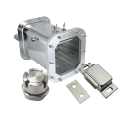
A friction hinge – also called a torque hinge or position hinge – uses internal friction to provide controlled rotational resistance. It holds a door, panel, lid, or display at any angle without external stays, gas struts, or locking mechanisms. Unlike a conventional hinge, which does exactly two things (connect two parts and let them rotate freely), a friction hinge does three: connect, rotate, and hold position on demand.
This distinction matters more than it sounds. In an industrial enclosure, that third function replaces a gas spring, a detent latch, and a separate stay arm – three components collapsed into one. Engineers call this capability “free-stop”: the panel stays wherever you leave it, at any angle, with no additional hardware. (Not to be confused with “detent” – preset angle stops – or “hold-open” – which only locks at the fully open position.)
You already use friction hinges every day. The laptop screen you’re reading this on holds its angle because of friction hinges, not loose pivots. Medical monitor arms, automotive center consoles, and industrial HMI panels all rely on the same principle. The hinge isn’t just connecting two parts – it’s managing gravity, vibration, and user force, all while fitting into a space smaller than a matchbox.
Understanding this changes how you approach design: you’re not picking a hinge from a catalog. You’re specifying a precision torque device.
How Friction Hinges Generate and Control Torque
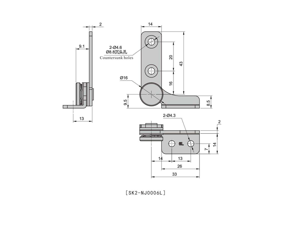
Before you can calculate torque or select materials, you need to understand what’s happening inside the hinge. “Friction hinge” is a category, not a mechanism – and the internal architecture determines everything about performance, lifespan, and cost. Three mainstream mechanisms solve fundamentally different engineering problems.
Spring-Clutch Mechanism – Constant Torque Through Wrapped Springs
The spring-clutch design is the gold standard for consistent, long-life torque. A hardened spring steel band – typically 301 stainless or beryllium copper – is tightly wound around a central shaft. The spring’s constant radial grip creates uniform friction at the shaft interface. As the hinge rotates, the spring slides against the shaft surface, and the friction force translates directly into rotational resistance.
What makes this mechanism special is its torque consistency. Across the full rotation range, torque varies less than ±15% from the nominal value. The shaft surface finish is the critical control parameter: Ra 0.2-0.4 μm is the sweet spot where friction is stable without excessive wear. Go rougher, and the torque becomes erratic. Go smoother, and you risk stick-slip.
Torque output scales with spring preload and shaft diameter, covering a practical range of 0.1-11.3 N·m. Lifespan is the mechanism’s headline number: Reell’s patented ReellTorq clip technology claims up to 50,000 cycles with zero readjustment. For comparison, a basic zinc die-cast friction hinge might last a few hundred cycles before torque drops below usable levels.
This is the mechanism to reach for when torque consistency and cycle life are your top priorities – medical monitor arms, aerospace seat-back trays, and any application where field adjustment isn’t practical.
Interleaved Plate Design – Scalable Torque Through Friction Discs
If the spring-clutch is a precision instrument, the interleaved plate design is a modular workhorse. Think of it as a miniature clutch pack: alternating friction discs, each keyed to opposite halves of the hinge, pressed together by a spring. When the hinge rotates, the discs slide against each other, and the cumulative friction across all disc interfaces produces the holding torque.
The engineering appeal is scalability. Torque = friction coefficient × spring normal force × effective disc radius × number of discs. Want 2× the torque? Double the disc count – no geometry changes needed. Disc materials range from hardened steel and bronze to carbon-fiber composites and paper-based friction materials (the same family used in automatic transmission clutch packs). Spring compression forces typically run 50-500 N, giving a per-disc torque contribution of 0.05-0.5 N·m.
The trade-off is wear. Those sliding disc interfaces degrade over time. Industry data suggests torque can drop 35-42% within 15,000 cycles on some interleaved-plate designs – a steep decline compared to the spring-clutch. This doesn’t make it a bad mechanism; it makes it the right mechanism for applications where torque is high but cycle count is moderate, and where periodic maintenance or replacement is acceptable. Heavy industrial equipment access doors and large enclosure lids fit this profile perfectly.
Pipe/Curl and Hybrid Mechanisms – Compact Solutions for Tight Spaces
Not every design has room for a multi-disc clutch pack. The pipe structure – a metal shaft press-fitted into an engineering plastic tube (typically POM acetal or PA66 nylon) – generates friction through radial interference alone. Torque depends on the interference fit and the polymer’s friction coefficient: a simple, elegant solution for torque ranges of 0.01-2.0 N·m, with a radial envelope as small as 2.5 mm.
The curl structure is similarly compact: a shaft rotates inside a curled spring sheet, using the sheet’s elastic recovery force to produce radial pressure against the shaft. Both mechanisms excel in consumer electronics – laptop hinges, tablet stands, POS terminals – where millimeter-scale packaging matters.
The critical limitation is temperature sensitivity. POM’s friction coefficient drops 15-25% between 20°C and 50°C, which means a hinge that holds perfectly at room temperature may sag on a hot day. For applications crossing wide temperature ranges, hybrid mechanisms that combine mechanical friction with viscous damping (silicone grease or hydraulic resistance) can smooth out the temperature-dependent behavior.
Torque Calculation – What the Basic Formula Won’t Tell You
Here is where most design guides stop: T = W × L(CG) × cos(θ). Multiply panel weight by the horizontal distance from the hinge pivot to the center of gravity, divide by the number of hinges, add a safety factor, and you’re done. It’s correct – in a freshman physics sense. And it’s the reason so many hinges “fail” in the field despite passing every calculation on paper.
The real problem isn’t the formula. It’s that the inputs are almost always incomplete.
The Core Formula and How to Apply It Correctly
Start with the formula, applied properly:
Tper hinge = (Weffective × LCG × cos(θmax)) / n
Where Weffective = total assembly weight (panel + all mounted hardware + handles + cable bundles + gasket compression force), LCG = horizontal distance from the hinge rotation axis to the assembly’s center of gravity when the panel is horizontal – measured from the pivot axis, not the panel edge, cos(θmax) = 1.0 at horizontal (your worst case), and n = number of hinges sharing the load.
Here’s a real worked example. Take an industrial control cabinet door:
| Load Component | Force (N) |
|---|---|
| Door panel + hardware (5.2 kg) | 51.0 |
| Cable bundle drag (8 cables, Ø12 mm each) | ~11.0 |
| EPDM gasket compression (30% compression) | ~6.0 |
| Effective W | 68.0 N |
With LCG = 0.30 m, cos(0°) = 1.0, and n = 2 hinges: Tper hinge = (68.0 × 0.30 × 1.0) / 2 = 10.2 N·m per hinge.
That’s the theoretical requirement. Now apply tolerance de-rating: friction hinge torque ratings typically carry a ±15% to ±25% manufacturing tolerance band. A hinge rated at 10.2 N·m might deliver as little as 7.65 N·m on the low end. To be safe, select a hinge with a rated torque of at least Tpeak / 0.80 = 1.25 × Tpeak. In this case: 12.75 N·m minimum rated torque.
Then add your environmental safety factor – 1.3× for stable indoor environments, 1.5× for temperature-variable or vibration-heavy installations, 1.5× minimum for medical or safety-critical applications. These factors stack: (1.25 tolerance) × (1.3 environment) = 1.625× over the raw calculated value.
For multi-hinge systems, mounting surface flatness must stay within 0.1 mm across all hinge mounting points. If surfaces aren’t coplanar, one hinge can carry 60-70% of the total load instead of its fair share – and that hinge will wear out first, cascading to the others.
The Four Hidden Loads That Cause Field Failures
Even with the formula applied correctly, four loads routinely get omitted from the calculation – and they’re responsible for the majority of field returns within 12-18 months of product launch.
Cable drag. Every cable, hose, or wire bundle that passes near the hinge axis adds bending resistance. A single Ø12 mm cable bent at a 50 mm radius contributes roughly 1.2-1.8 N of equivalent force. Eight such cables – common in an industrial HMI cabinet – add 10-15 N that never appeared in the original panel-weight calculation.
Gasket compression. EPDM sealing gaskets are springs in disguise. At 30% compression, a Shore A 60-70 EPDM gasket exerts 3-8 N of reaction force per linear meter. On a 2-meter door perimeter, that’s 6-16 N fighting against the hinge. It’s a small number next to the panel weight, but when you’re already close to the torque margin, it’s enough to tip the balance.
Temperature effects on friction materials. This is the most insidious hidden load because it’s invisible at room temperature. Polymer friction pads (POM, nylon, acetal) lose 15-25% of their friction coefficient between 20°C and 50°C. Your hinge passes bench testing at 22°C, ships to a customer in Southeast Asia or the American Southwest, and starts sagging by August. The fix: always spec based on the hinge’s torque value at the highest expected operating temperature, not the room-temperature rating. Ask the supplier for a torque-vs-temperature curve from -20°C to +80°C, with steps no larger than 10°C.
Mounting misalignment. Two hinges on surfaces that aren’t coplanar within 0.1-0.2 mm create an asymmetric load distribution. The tighter hinge carries disproportionately more load, wears faster, and eventually fails – at which point the remaining hinge is suddenly carrying 100% of a load it was never sized for. The fix is mechanical, not calculational: use an installation fixture or jig to guarantee alignment, and for critical applications, specify hinges with slotted mounting holes that allow micro-adjustment after installation.
Material Selection – Matching the Hinge to Its Environment
Torque math gets you the number. Material selection makes sure that number holds over time, across temperature swings, and through whatever chemicals your application throws at it. There is no universally “best” material – only the right material for your specific environment.
| Material | Torque Stability | Corrosion | Temp. Range | Torque Range | Weight | Cost | Best For |
|---|---|---|---|---|---|---|---|
| SUS304 | ★★★★ | ★★★ | -40~120°C | 0.5 – 15 N·m | Heavy | $$ | General industrial |
| SUS316 | ★★★★ | ★★★★★ | -40~120°C | 0.5 – 15 N·m | Heavy | $$$ | Marine, medical, food |
| Zinc Alloy | ★★★ | ★★ | -20~80°C | 0.1 – 5 N·m | Medium | $ | Consumer electronics |
| Aluminum | ★★★ | ★★★★ | -40~100°C | 0.1 – 8 N·m | Light | $$ | Aerospace, portable |
The SUS304 vs. SUS316 distinction deserves emphasis because it’s one of the most common material selection errors. The difference is molybdenum: SUS316 contains 2-3% Mo, which dramatically improves resistance to chloride pitting. If your application sees salt spray (marine), disinfectant chemicals (medical), or acidic cleaning agents (food processing), the cost premium for 316 over 304 is negligible compared to the cost of a corrosion-related field failure.
Zinc alloy has a temperature ceiling that’s easy to overlook: above 80°C, zinc alloys enter the creep regime, where sustained load produces permanent deformation. Aluminum hinges must be anodized – bare aluminum at a friction interface generates abrasive aluminum oxide particles almost immediately, accelerating wear.
If you’re unsure which category your environment falls into, ask three questions: Is there any saltwater or disinfectant contact? Does the operating temperature exceed 60°C? Is weight a binding constraint? The answers will eliminate at least two of the four options.
Surface treatments can make or break your material choice. Passivation on stainless steel improves corrosion resistance but can lower the friction coefficient at the interface – you might gain rust protection and lose holding torque in the same step. Hard anodizing on aluminum creates a wear-resistant surface layer, but the coating thickness (typically 10-25 μm) changes the effective shaft diameter. Before locking in a surface treatment, ask your supplier for friction coefficient data on the treated surface, not just the base material.
Matching Friction Hinge Types to Real-World Applications
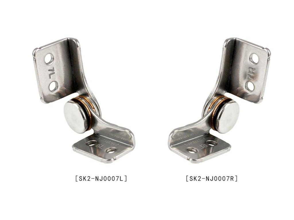
Everything covered so far – mechanisms, torque math, materials – converges at the application level. Here’s how the pieces fit together across five major industrial contexts.
Industrial equipment and automation demands heavy payloads in vibration-rich environments. The combination calls for constant-torque spring-clutch mechanisms in SUS304, with torque values calculated using the full Weffective method (cables + gaskets included). HMI operator panels, safety guard doors, and electrical enclosure access hatches are the canonical use cases. If the door is opened and closed multiple times per shift, cycle life matters as much as peak torque.
Medical equipment adds hygiene to the requirements list. Surgical light arms, ultrasound monitor mounts, and diagnostic cart lids need precise positioning – the device must stay exactly where the clinician places it – plus surfaces that resist bacterial colonization. SUS316 with electropolished finish is standard here, with constant-torque mechanisms providing the “moves when pushed, stays when released” feel that clinicians rely on.
Automotive and transportation imposes the tightest packaging constraints. Center console lids, fold-out tray tables, seat-back displays, and overhead bins all need friction hinges that fit into millimeter-scale envelopes. Pipe-structure or curl-structure mechanisms dominate here, often with hybrid damping to deliver the premium “slow-open” feel that consumers associate with build quality. Interior components must also meet head-impact standards (FMVSS 201 in the US market).
Consumer electronics represents the high-volume end of the spectrum. Laptop hinges, tablet stands, and POS terminal mounts are produced in the millions, making cost-per-unit the dominant variable. Pipe-structure mechanisms with POM friction elements deliver adequate performance at the right price point. The design challenge here isn’t torque – it’s maintaining consistent friction feel across 20,000+ open/close cycles despite a $0.30 bill of materials.
Cold storage and cold chain introduces a counterintuitive problem: low-temperature lubrication. Standard greases thicken or freeze below -20°C, turning a smooth hinge into a sticky one. Low-temperature synthetic greases that maintain flow at -40°C are mandatory. SUS304 or 316 stainless is the default material choice – zinc alloys become brittle at cold-chain temperatures, and aluminum’s higher thermal conductivity can cause condensation freezing at the hinge interface.
Here’s the decision sequence that ties it all together: start with your environment and load profile. Pick a mechanism that matches your dominant constraint – consistency, scalability, or space. Calculate torque with every hidden load included. Select the material that survives your operating conditions. Then validate with testing. Skip any step and the hinge won’t fail in the CAD model. It’ll fail in the field.
Need a friction hinge spec’d for your specific application and environment? Our engineering team can help with torque calculations and material selection for your exact operating conditions.
Request Engineering SupportFailure Prevention – The Engineer’s Pre-Production Checklist
Here’s the uncomfortable truth: more than 60% of friction hinge “failures” aren’t manufacturing defects. They’re design omissions – a load that wasn’t counted, an environmental factor that wasn’t considered, or a validation step that was skipped to meet a schedule. The hinge itself was fine. The specification was incomplete.
The Three Most Common Failure Modes – Ranked by Field Frequency
#1: Cable drag omission (highest frequency). The panel was weighed on a bench. The cables were installed on the assembly line. Nobody added them together in the torque calculation. The result: a door that holds position on Day 1 but droops within weeks as the hinge’s initial torque margin gets consumed by the unaccounted cable resistance. The typical discovery window is 12-18 months after product launch – enough time for units to ship, accumulate use cycles, and generate customer complaints that reference “design flaw,” not “installation error.”
Prevention is straightforward: during the design phase, list every flexible component (cables, hoses, wire looms, pneumatic tubes) that passes within 100 mm of the hinge rotation axis. Estimate the bending resistance of each. Add the total to Weffective.
#2: Temperature-induced torque decay (most deceptive). The hinge passed every bench test – at 22°C, in an air-conditioned lab. But the product ships globally, and the customer’s installation is in an unshaded outdoor cabinet in Texas, where internal temperatures reach 55°C by mid-afternoon. The polymer friction elements that worked perfectly at room temperature have lost 20% of their friction coefficient, and the door that held at 85° now sags to 60°.
The only prevention is data. Request torque-vs-temperature curves from your supplier, covering your full operating range. For polymer-based friction elements (POM, PA66), treat 50°C as a hard inflection point – above this temperature, torque decay accelerates non-linearly.
#3: Mounting misalignment (most overlooked). Two hinges, two mounting surfaces, and a tolerance stack-up that nobody checked. When the mounting surfaces deviate by more than 0.2 mm from coplanarity, one hinge carries 60-70% of the load. It wears faster, develops play, and transfers even more load to the surviving hinge – a cascade that ends with a dropped door. The fix is a combination of good fixturing during assembly and, for high-value applications, specifying hinges with slotted or floating mounting provisions.
The Pre-Production Design Validation Checklist
Before releasing your friction hinge specification to production, run through these eight checks. If time allows only one, make it #7 – high-low temperature cycle testing under load. It’s the single test that comes closest to predicting real-world performance.
A final note on supplier selection: the difference between a hinge supplier and a hinge engineering partner often comes down to whether they can provide items 5 and 7 proactively – test data, not just catalog specs. Manufacturers with in-house R&D and dedicated testing labs, such as Kunlong Hardware, can supply torque-temperature characterization curves and cycle-life validation reports alongside samples, giving you the data needed to complete the checklist without running every test in-house. For specific torque profiles or environmental requirements, you can reach their engineering team through their friction hinge engineering guide or contact page.